Table of Contents
Advertisement
Quick Links
®
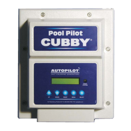
Pool Pilot
Cubby Digital
Salt Chlorine Generator
Swimming Pool & Spa Purification System
Models: 75080 and 75081
For use with SC-36 Cell, ONLY!
Owner's
Manual
Installation and Operation
This manual covers the installation and oper-
ation of Cubby Digital Chlorine Generators
equipped with the following Cell & Manifold
assemblies (sold separately), Part Numbers:
94105 & 75082.
IMPORTANT !
Read This Manual Before
Installing or Operating
INSTALLER: T
D
P
'
P
R
E
O
HIS
OCUMENT IS
URCHASER
S
ROPERTY AND IS TO
EMAIN WITH THE
QUIPMENT
WNER
1
Advertisement
Chapters
Table of Contents

Summary of Contents for Aquacal Pool Pilot Cubby Digital
- Page 1 ® Pool Pilot Cubby Digital Salt Chlorine Generator Swimming Pool & Spa Purification System Models: 75080 and 75081 For use with SC-36 Cell, ONLY! Owner’s Manual Installation and Operation This manual covers the installation and oper- ation of Cubby Digital Chlorine Generators equipped with the following Cell &...
-
Page 3: Table Of Contents
OWNER TABLE OF CONTENTS WELCOME TO THE TEAM ....................5 FACTORY CONTACT INFORMATION ................6 SAFETY INFORMATION ..................... 7 Safety Signals ......................... 7 Safety Information Main Table ....................7 OWNER QUICK START & RUN ..................9 How Your Chlorine Generator Works ..................9 Control Overview ........................9 UP and DOWN Arrows .................... - Page 4 SECTION SYMBOLS Contact the Factory Owner - Operator Quick Start Specifications Installation Installation Programming & Setup Reference Tables Maintenance Troubleshooting...
- Page 5 Dear Owner: ongratulations on your wise decision to make an AquaCal AutoPilot chlorinator a part of your home. Just add salt, and let your Cubby produce the chlorine to sanitize your pool or spa. And, a wonderful thing happens to the salt after it is turned into chlorine and does the work of sanitizing the water—it turns back into salt and the process begins all over...
- Page 6 CONTACT INFORMATION What We Need to Know If You need To Contact Us... If you should need to call AquaCal AutoPilot for questions, service, or parts, please have the following information ready: INSTALLER - Please record the following information prior to installation:...
-
Page 7: Safety Information
"Troubleshooting," you will be able to determine if a call for service is required. Your installer can be one source of service, or AquaCal AutoPilot Customer Support personnel stand ready to assist you at: (800) 786-7751. For questions concerning installation, operation, service and upkeep, please contact your installer or AquaCal AutoPilot Customer Support. - Page 8 Failure to heed the following may result in equipment CAUTION ! damage. The AquaCal AutoPilot Chlorinator must be installed and operated as specified. Failure to do so will void the equipment warranty. A Note Concerning Terminology: Throughout this manual, the portion of the system which mounts to the wall (and powers the cell) may be referred to as the: Cubby Digital, Pool Pilot, power center, control center, or unit.
-
Page 9: Owner Quick Start & Run
OWNER QUICK START & RUN The Pool Pilot Cubby Digital is a salt chlorination system designed for pool or spa water purification. Although the Pool Pilot is easy to use, it is important to read through the entire manual before attempting to operate the system. -
Page 10: The Boost Button
OWNER QUICK START & RUN (CONTINUED) The Boost Button: The BOOST button increases output to 100%. Use this feature when a heavier that normal bather load is anticipated. Press BOOST once......= 24-Hour Boost Press and hold BOOST for 8 seconds = 72-Hour Boost Press BOOST a second time.... -
Page 11: Water Balance & Chemistry Recommendations
OWNER QUICK START & RUN (CONTINUED) Water Balance & Chemistry Recommendations Proper water balance is critical to the operation of your Cubby Sanitizer. Conditions such as high pH levels, low cyanuric acid (stabilizer ) levels, or other factors causing unbalanced water, will mask the sanitizer production of your Cubby. -
Page 12: Important Features
IMPORTANT FEATURES Patented temperature compensation for chlorine output control... Programmable microprocessor control... Multi-language digital display (English, Spanish, & French)... Digitally controlled power to the SuperCell... Tri-sensor circuitry to monitor water flow, water temperature, and salt level. Calculates and provides recommended salt addition amounts required to maintain the recommended 3000 ppm (3.0 g/l)) salt concentration level. - Page 13 &7 ® Pool Pilot Cubby Digital Salt Chlorine Generator Swimming Pool & Spa Purification System Models: 75080 and 75081 For use with SC-36 Cell, ONLY! This manual covers the installation and operation of Cubby Digital Chlorine Generators equipped with the following Cell & Manifold as- semblies (sold separately): Part Numbers 94105 &...
-
Page 14: Installer Table Of Contents
INSTALLER TABLE OF CONTENTS FACTORY CONTACT INFORMATION ................6 SAFETY INFORMATION ..................... 7 Safety Signals ......................... 7 Safety Information Main Table ....................7 SPECIFICATIONS ......................16 Input Electrical Power ......................16 Chlorine Output ........................16 Manifold Flow Requirements ....................16 Agency Approvals ........................16 INSTALLATION ......................... -
Page 15: Salt Addition Chart
INSTALLER TABLE OF CONTENTS (CONTINUED) MENU OVERVIEW .......................... 26 ACCESS TO PROGRAMMING ..................... 26 Control Panel ......................... 26 Operation of Buttons ......................... 26 Menus ............................26 PROGRAMMING ..........................27 Menu Button ..........................27 Select Button .......................... 27 View Setup ..........................27 Programming at Installation .................... -
Page 16: Specifications
Visit www.autopilot.com for latest manual revisions and helpful troubleshooting tips. -or- Run the “View Setup” (page-27) and record the information displayed; have the following information available prior to contacting AquaCal AutoPilot Customer Support: Current Measured Salt Level Software (SW) Versions Contact factory Customer Support by dialing: (800) 786-7751 or (727) 823-5642... -
Page 17: Installation
INSTALLATION A Note Concerning Terminology: Throughout this manual, the portion of the system which mounts to the wall (and powers the cell) may be referred to as the: Cubby Digital, Pool Pilot, power center, control center, or unit. In addition, when “pool” is referred to in the absence of the word “spa,”... -
Page 18: Inline-Cell Manifold Assembly (#75082)
INSTALLATION (CONTINUED) Two Available Water Manifolds Assemblies: Inline-Cell Manifold Assembly (#75082) The manifold is connected into the plumbing after all other equipment. Water from the pool/spa is moved though the manifold by the circulation pump. The man- ifold's key components are the Tri-Sensor and SuperCell. The Tri-Sensor provides data (from electronic sensors) to the Control Unit for monitoring water flow, water temperature, and salt concentration level. - Page 19 INSTALLATION (CONTINUED) Basic System Overview: The Cubby Digital unit is a salt chlorination system for pool or spa purification, and is designed to operate in the following configurations: Shown with Inline-Cell Manifold Assembly (#75082) Circuit Timer Breaker ROKEN LINES REPRESENT ELECTRICAL SUPPLY POWER SOURCE OPTIONS IMER REAKER...
-
Page 20: Installation Steps
INSTALLATION (CONTINUED) Installation Steps: Details on each step of the installation process are presented on the following pages: 1. Plumbing the Manifold Assembly (see below) 2. Mounting the Control Unit (page-21) 3. Electrical Requirements & Connections (pages 21-22-23) a. Grounding and bonding b.
Need help?
Do you have a question about the Pool Pilot Cubby Digital and is the answer not in the manual?
Questions and answers