
Summary of Contents for Brightwell Nexus Laundry System
- Page 1 Nexus Laundry System Instruction Manual Installation and setup Brightwell.co.uk Revision 1.1 02/2021 M0261 EN...
-
Page 2: Table Of Contents
CONTENTS GENERAL INFORMATION SAFETY INFORMATION --------------------------------------------------------------------------------------------------------------------------------------------------A-1 SAFETY PRECAUTIONS -------------------------------------------------------------------------------------------------------------------------------------------------A-2 WARRANTY --------------------------------------------------------------------------------------------------------------------------------------------------------------------A-2 --------------------------------------------------------------------------------------------------------------------------------------------------------------------A-3 OPERATION TECHNICAL INFORMATION BEFORE INSTALLATION -------------------------------------------------------------------------------------------------------------------------------------------------B-1 ---------------------------------------------------------------------------------------------------------------------------------------B-2 TECHNICAL SPECIFICATIONS LAYOUT - MAIN UNIT SCREEN ---------------------------------------------------------------------------------------------------------------------------------------B-4 LAYOUT - MAIN PCB -------------------------------------------------------------------------------------------------------------------------------------------------------B-5 LAYOUT - IO BOARD ------------------------------------------------------------------------------------------------------------------------------------------------------B-6 LAYOUT - FORMULA SELECT SCREEN --------------------------------------------------------------------------------------------------------------------------B-7 UNIT VARIATIONS -----------------------------------------------------------------------------------------------------------------------------------------------------------B-8... - Page 3 CONTENTS CONNECTING CHEMICAL ----------------------------------------------------------------------------------------------------------------------------------------------D-4 INPUT INFORMATION AND FIRMWARE -------------------------------------------------------------------------------------------------------------------------D-6 PUMP PRIME SCREEN ---------------------------------------------------------------------------------------------------------------------------------------------------D-7 --------------------------------------------------------------------------------------------------------------------------------------D-8 FLUSH VALVE PRIME SCREEN ------------------------------------------------------------------------------------------------------------------------D-9 FLUSH VALVE & PUMP PRIME SCREEN FLUSH VALVE & PUMP PRIME SCREEN ---------------------------------------------------------------------------------------------------------------------- D-10 MANIFOLD AND FLUSH SETTINGS ------------------------------------------------------------------------------------------------------------------------------ D-11 PUMP SPEED/FLOW RATE AND CALIBRATION ----------------------------------------------------------------------------------------------------------- D-13 PUMP SPEED/FLOW RATE AND CALIBRATION ----------------------------------------------------------------------------------------------------------- D-14...
- Page 4 CONTENTS SETTINGS - WIFI SETTINGS ----------------------------------------------------------------------------------------------------------------------------------------- F-17 ----------------------------------------------------------------------------------------------------------------------- F-19 SETTINGS - MQTT BROKER SETTINGS SETTINGS - RF SETTINGS ------------------------------------------------------------------------------------------------------------------------------------------- F-20 SETTINGS - SET BLUETOOTH POWER ------------------------------------------------------------------------------------------------------------------------ F-24 SETTINGS - CYCLE COUNTERS ---------------------------------------------------------------------------------------------------------------------------------- F-26 FORMULA SELECT FORMULA SELECT - PUMP STOP ----------------------------------------------------------------------------------------------------------------------------------G-2 FORMULA SELECT - PRIME PUMP ---------------------------------------------------------------------------------------------------------------------------------G-3...
-
Page 5: General Information
GENERAL INFORMATION Section... -
Page 6: Safety Information
GENERAL INFORMATION SAFETY INFORMATION Please read the following precautions carefully before using this equipment. This unit contains high voltage circuits that may expose you to the danger of electric shock. Means for disconnection must be incorporated in accordance with the wiring rules. -
Page 7: Safety Precautions
GENERAL INFORMATION SAFETY PRECAUTIONS Please read the following precautions carefully before using this equipment. This appliance can be used by children aged from 8 years and above and persons with reduced physical, sensory or mental capabilities or lack of experience and knowledge if they have been given supervision or instruction concerning use of the appliance in a safe way and understand the hazards involved. -
Page 8: Operation
GENERAL INFORMATION OPERATION The Nexus Laundry units, are automatic dosing systems designed for use with commercial washing machines. The units are intended for indoor, fixed installation only. The means of disconnection must be incorporated in the fixed wiring, with an air gap of at least 3mm in each pole. The pumps are initiated by applying signals of between 90V and 240V AC or DC across the corresponding Inputs of the A and B rails on the power board. -
Page 9: Technical Information
TECHNICAL INFORMATION Section... -
Page 10: Before Installation
9 way connector x 2 SOLUZIONI DI EROGAZIONE RIVOLUZIONARIE Quick start Guide x 1 Nexus Quickstart Nexus Quickstart Instruction Manual Manuale di istruzioni Installation and Information Installazione e informazioni Brightwell.co.uk Brightwell.co.uk Revisione 1.0 Revision 1.0 02/2021 02/2021 M0000 M0000 OPTIONAL (Based on order) Formula Select 1-6 Revision 1.1... -
Page 11: Technical Specifications
TECHNICAL INFORMATION TECHNICAL SPECIFICATIONS VOLTAGE 100–240V AC / 50–60Hz 1 - 4 Pump: 2.3A (240V) 5 Pump: 3.8A (240V) FREQUENCY 6 Pump: 5.3A (240V) 7 Pump: 6.8A (240V) 8 Pump: 8.3A (240V) POWER 1 Pump: 75W SUPPLY 5 Pump: 103W CURRENT 6 Pump: 131W 7 Pump: 159W... - Page 12 TECHNICAL INFORMATION MAIN DISPLAY KEYPAD DISPLAY KEYPAD ENCLOSURE ADDITIONAL PUMP MODULE ENCLOSURE MEMBRANE PUMP FORMULA SELECT DISPLAY KEYPAD ENCLOSURE Revision 1.1 04/2022 M0261 EN...
-
Page 13: Layout - Main Unit Screen
TECHNICAL INFORMATION LAYOUT - MAIN UNIT SCREEN PUMP ------------ (MESSAGE) NUMBER OF PUMPS FAULT MESSAGE ANY RUNNING PUMPS Displays the number of connected If there are any errors on the unit, If any pumps are running, they will pumps to the unit the message will show here display here Revision 1.1... -
Page 14: Layout - Main Pcb
TECHNICAL INFORMATION LAYOUT - MAIN PCB 6. MULTIDOSE AND/OR 1. PAIR BUTTON FLOW SENSOR MODULE 7. MANIFOLD & SAFETY 2. ETHERNET STOP SWITCHES 3. MOTOR 8. FLOAT SWITCHES CONNECTORS 9. 24 VOLT POWER 4. ADD ON PUMP 5. IOM Revision 1.1 04/2022 M0261 EN... -
Page 15: Layout - Io Board
TECHNICAL INFORMATION LAYOUT - IO BOARD 12 34 56 78 9 6. CONNECTION TO 1. MAINS POWER IN MDU/PREVIOUS IOM 7. OUTPUT TO IOM 2. MAINS OUT 8. 24 VOLT OUT 3. COMMON NEUTRAL 4. TRIGGER INPUT 9. FORMULA SELECT 5. -
Page 16: Layout - Formula Select Screen
TECHNICAL INFORMATION LAYOUT - FORMULA SELECT SCREEN PG01 000000 Program Name PROGRAM RUN COUNT PROGRAM NUMBER PROGRAM NAME Revision 1.1 04/2022 M0261 EN... -
Page 17: Unit Variations
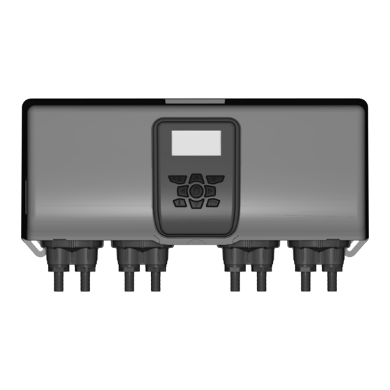
TECHNICAL INFORMATION UNIT VARIATIONS 4 PUMP VARIANT 5 PUMP VARIANT 6 PUMP VARIANT 7 PUMP VARIANT Revision 1.1 04/2022 M0261 EN... - Page 18 TECHNICAL INFORMATION UNIT VARIATIONS 8 PUMP VARIANT Revision 1.1 04/2022 M0261 EN...
-
Page 19: Mounting & Wiring
MOUNTING & WIRING Section... -
Page 20: Mounting To The Wall - 4 Pump System
MOUNTING & WIRING MOUNTING TO THE WALL - 4 PUMP SYSTEM STEP 1 Place the unit against the wall where you would like to MA X install. 2 metres 2 METRES PLEASE NOTE - The unit should not be more than 2 metres from the chemical. - Page 21 MOUNTING & WIRING MOUNTING TO THE WALL - 4 PUMP SYSTEM STEP 5 Take the wall plug and place into the drilled hole. If required, use a hammer or mallet (not provided) to drive flush. STEP 6 Take the M5 screw from the pack and use a screwdriver M5 Pozi (not provided) to screw into the wall.
- Page 22 MOUNTING & WIRING MOUNTING TO THE WALL - 4 PUMP SYSTEM STEP 9 Once straight, take your marker and place a dot inside the bottom mounting holes. Try to get them as central as possible. STEP 10 Remove the unit from the wall to reveal the drill marks. STEP 11 Drill two holes using the same 6mm drill bit as before (not provided).
- Page 23 MOUNTING & WIRING MOUNTING TO THE WALL - 4 PUMP SYSTEM STEP 13 Place the unit back over the original screw mount. STEP 14 Align the unit using the spirit level located on the bottom M5 Pozi of the unit with the wall plugs. Take the M5 pozi screws provided and screw into place.
-
Page 24: Mounting To The Wall 5 - 8 Pump System
MOUNTING & WIRING MOUNTING TO THE WALL 5 - 8 PUMP SYSTEM STEP 1 Place the unit against the wall where you would like to install. 2 METRES 2 metres PLEASE NOTE - The unit can not be more than 2 metres from the chemical. - Page 25 MOUNTING & WIRING MOUNTING TO THE WALL 5 - 8 PUMP SYSTEM STEP 5 Take the wall plug and place into the drilled hole. If re- quired, use a hammer or mallet (not provided) to drive flush. STEP 6 Take the M5 screw from the pack and use a screwdriver M5 Pozi (not provided) to screw into the wall.
- Page 26 MOUNTING & WIRING MOUNTING TO THE WALL 5 - 8 PUMP SYSTEM STEP 9 Once straight, take your marker and place a dot inside the bottom mounting holes for the main unit and all the additional pumps. Try to get them as central as possible. STEP 10 Remove the unit from the wall to reveal the drill marks.
- Page 27 MOUNTING & WIRING MOUNTING TO THE WALL 5 - 8 PUMP SYSTEM STEP 13 Place the unit back over the original screw mount. STEP 14 Align the unit using the spirit level located on the bottom of the unit with the wall plugs. Take the M5 pozi screws M5 Pozi provided and screw into place.
-
Page 28: Wiring Guide - Power
MOUNTING & WIRING WIRING GUIDE - POWER STEP 1 Remove the screws from the bottom of the main unit. (as illustrated) M4 POZI STEP 2 Pull the front cover up PLEASE NOTE - The screen is attached, with wires, take care not to damage when detaching the cover. STEP 3 Use the hooks at the top of the enclosure to hold the cover in place. - Page 29 C-10 C-10 MOUNTING & WIRING WIRING GUIDE - POWER STEP 5 Remove the 3 way green connector on the power supply EARTH NEUTRAL (as illustrated). Place the 3 core mains wire rated 110- LIVE 240 AC into the slot located on the IO board. M3 POZI Revision 1.1 04/2022...
-
Page 30: Wiring Guide - Trigger Signals
C-11 C-11 MOUNTING & WIRING WIRING GUIDE - TRIGGER SIGNALS STEP 1 The TRIGGER SIGNALS are located inside the unit on the right side board (as illustrated). Wire these into the signals on the washing machine. STEP 2 These are the COMMON NEUTRAL connector. STEP 3 These are the ISOLATED NEUTRAL connectors. - Page 31 C-12 C-12 MOUNTING & WIRING WIRING GUIDE - TRIGGER SIGNALS STEP 3 The left hand side 2 way connector is the common ground. Wire this in if you have a common neutral for the NEUTRAL trigger signals. M3 POZI STEP 4 Now that you have connected the common ground, you can wire in the trigger signals from the machine.
-
Page 32: Wiring Guide - Auto Formula Select Timed
C-13 C-13 MOUNTING & WIRING WIRING GUIDE - AUTO FORMULA SELECT TIMED STEP 1 The 9th input on the connector is for the AUTO FORMULA SELECT. Seen here: AFS - 9 M3 POZI STEP 2 Use this connection to set up either TIMED or BINARY 1 Second formula select signals. -
Page 33: Wiring Guide - Auto Formula Select Binary
C-14 C-14 MOUNTING & WIRING WIRING GUIDE - AUTO FORMULA SELECT BINARY STEP 1 For BINARY mode you first apply the MODE signal, then you have the SET UP TIME in section (Add section here). To activate the program you will need to put the correlating binary code with the correct trigger. -
Page 34: Wiring Guide - Manifold
C-15 C-15 MOUNTING & WIRING PROGRAM NO. INPUT 1 INPUT 2 INPUT 3 INPUT 4 INPUT 5 PROGRAM 26 PROGRAM 27 PROGRAM 28 PROGRAM 29 PROGRAM 30 WIRING GUIDE - MANIFOLD STEP 1 The manifold connectors are located inside the main unit, in the position illustrated here. -
Page 35: Wiring Guide - Manifold And Safety Switch
C-16 C-16 MOUNTING & WIRING WIRING GUIDE - MANIFOLD AND SAFETY SWITCH STEP 1 The manifold connectors are located inside the main unit, in the position illustrated here. STEP 2 The wiring for the connector is show here, the top two Neutral are the 24 volt and neutral for the manifold. -
Page 36: Programming The Unit
PROGRAMMING THE UNIT Section... - Page 37 PROGRAMMING THE UNIT PRIME BUTTON PUMP STOP/STANDBY MODE SKIP BUTTON ARROW NAVIGATION PROGRAM BUTTON TEST BUTTON MOVE FORWARD AND MOVE UP AND DOWN BACK CHANGE SETTING Revision 1.1 04/2022 M0261 EN...
-
Page 38: Initial Setup
PROGRAMMING THE UNIT INITIAL SETUP ENGLISH STEP 1 When the unit is first boots, you will be asked to select Advance a language. Use the UP and DOWN keys to change. Pressing RIGHT to advance to the next screen. Change Language SET DATE &... - Page 39 PROGRAMMING THE UNIT INITIAL SETUP UNIT OF MEASUREMENT STEP 5 TIME The final screen will allow you to switch the unit of mea- Advance surement from TIME to ML, FL. OZ or GRAMS. Use the UP and DOWN arrow to change selection. RIGHT arrow to confirm.
-
Page 40: Connecting Chemical
PROGRAMMING THE UNIT CONNECTING CHEMICAL STEP 1 Connect the threaded pipe to the pump connectors (as illustrated). STEP 2 Take the zip ties (provided) and attach to the top of the pipe to create a tight seal. STEP 3 It is recommended to use snips to remove any excess left on the tie (as illustrated). - Page 41 PROGRAMMING THE UNIT CONNECTING CHEMICAL STEP 5 Ensure that the chemical is located no further than 2 metres away from the pump. 2 metres STEP 6 Once you have all the inlet and outlet tubes connected correctly, you will need to PRIME the pumps to get the chemical ready for delivery.
-
Page 42: Input Information And Firmware
PROGRAMMING THE UNIT INPUT INFORMATION AND FIRMWARE PUMP - - - - - - - BRIGHTWELL STEP 1 From the main screen press the UP button will take you to the Wash Cycle screen. Input Information IP 1-0 2-0 3-0... -
Page 43: Pump Prime Screen
PUMP PRIME SCREEN STEP 1 From the main screen press the PRIME button on the Pumps keypad to move to the prime pump screen. Brightwell Note: If a manifold has been assigned the pump and flush will prime together. Prime PRIME MODE... -
Page 44: Flush Valve Prime Screen
PROGRAMMING THE UNIT FLUSH VALVE PRIME SCREEN STEP 1 Pumps From the main screen press the PRIME button on the Brightwell keypad to select the Pump Prime screen. Prime PRIME FLUSH VALVE STEP 2 From the Pump Prime menu, press the TEST button to select to the Flush Valve menu. - Page 45 PROGRAMMING THE UNIT FLUSH VALVE & PUMP PRIME SCREEN STEP 5 Pumps From the main screen press the PRIME button on the Brightwell keypad to move to the Pump Prime screen. Prime PRIME FLUSH VALVE STEP 6 From the Pump Prime menu, press the TEST button to take you to the Flush Valve menu.
-
Page 46: Flush Valve & Pump Prime Screen
D-10 D-10 PROGRAMMING THE UNIT FLUSH VALVE & PUMP PRIME SCREEN PRIME FLUSH VALVE AND PUMP 1 STEP 9 When the correct valve and pump is selected, press and hold the REPORTS button on the keypad to prime. Revision 1.1 04/2022 M0261 EN... -
Page 47: Manifold And Flush Settings
D-11 D-11 PROGRAMMING THE UNIT MANIFOLD AND FLUSH SETTINGS ENTER STEP 1 PASSCODE From the first screen, press the RIGHT arrow and enter ---- the pass code to proceed. Advance STEP 2 OPERATIONAL Press the RIGHT arrow to navigate to the Flush Manifold SETTINGS Settings. - Page 48 D-12 D-12 PROGRAMMING THE UNIT MANIFOLD AND FLUSH SETTINGS FLUSH SETTING STEP 5 BEFORE AND The next screen will show the Flush Settings. You can AFTER Advance change this between ‘BEFORE and AFTER’ to ‘AFTER ONLY’ using the UP and DOWN arrow. Press the RIGHT arrow to advance and save each setting.
-
Page 49: Pump Speed/Flow Rate And Calibration
D-13 D-13 PROGRAMMING THE UNIT PUMP SPEED/FLOW RATE AND CALIBRATION ENTER STEP 1 PASSCODE From the main screen, press the RIGHT arrow and enter ---- the pass code to proceed forward. Advance STEP 2 OPERATIONAL Press the RIGHT key to advance to the Operational SETTINGS Settings menu. - Page 50 D-14 D-14 PROGRAMMING THE UNIT PUMP SPEED/FLOW RATE AND CALIBRATION PUMP SPEED 100% STEP 5 Confirm & From here, you can change the Pump Speed using the Advance UP or DOWN arrow. Adjust Speed STEP 6 PUMP SPEED To calibrate the pump press the PRIME button once to Enter display the calibration menu.
-
Page 51: Pump Stop Mode
D-15 D-15 PROGRAMMING THE UNIT PUMP STOP MODE PUMP STOP STEP 1 MODE To stop a pump from running, press the PUMP STOP OFF ---------- button located on the main keypad. ON 12345678 Pump Stop PUMP STOP MODE STEP 2 OFF ---------- To deactivate a pump, use the RIGHT and LEFT arrow ON 12345678... -
Page 52: Change Unit Mode
D-16 D-16 PROGRAMMING THE UNIT CHANGE UNIT MODE ENTER STEP 1 PASSCODE From the main screen, press the RIGHT arrow and enter ---- the pass code to proceed forward. Advance OPERATIONAL SETTINGS STEP 2 You will be placed on the Operational Settings menu. Use the UP or DOWN arrows to navigate to the SYSTEM SETTINGS menu. - Page 53 D-17 D-17 PROGRAMMING THE UNIT CHANGE UNIT MODE STANDARD STEP 5 MODE The default for the unit will be Standard Mode. Use the Advance UP or DOWN arrow to change to the mode you want to use. Press the RIGHT arrow to advance and save each setting.
-
Page 54: Change Unit Of Measurement
D-18 D-18 PROGRAMMING THE UNIT CHANGE UNIT OF MEASUREMENT ENTER STEP 1 PASSCODE From the main screen press the RIGHT arrow and enter ---- the pass code to proceed forward. Advance OPERATIONAL SETTINGS STEP 2 You will be placed on the Operational Settings menu. Use the UP or DOWN arrows to navigate to the SYSTEM SETTINGS menu. - Page 55 D-19 D-19 PROGRAMMING THE UNIT CHANGE UNIT OF MEASUREMENT UNIT OF MEASURE STEP 5 Use the UP and DOWN arrow to select the unit of TIME measurement you wish to use. You can choose between Confirm TIME(MS), ML, GRAMS and FL OZ. Once you have the unit you wish to use highlighted.
-
Page 56: Creating A Washprogram
CREATING A WASHPROGRAM Section... -
Page 57: Creating A Program - Standard Mode
CREATING A WASHPROGRAM CREATING A PROGRAM - STANDARD MODE STEP 1 ENTER If your unit is not currently in Standard Mode please refer PASSCODE to Changing Unit Mode section (Page 48). From the ---- main screen press the RIGHT arrow and enter the pass Advance code to proceed forward. - Page 58 CREATING A WASHPROGRAM CREATING A PROGRAM - STANDARD MODE SIGNAL ACCEPTANCE TIME STEP 5 1 SECOND On this screen you can edit the Signal Acceptance Time Advance using the UP and DOWN arrows. Press the RIGHT arrow to advance and save the setting. Change Time PROGRAM STEP 6...
- Page 59 CREATING A WASHPROGRAM CREATING A PROGRAM - STANDARD MODE PRO 01 INPUT 01 STEP 9 PUMP 1 After the initial settings have been set, you will be able ENABLED to activate the pumps that will run on the particular Advance input.
- Page 60 CREATING A WASHPROGRAM CREATING A PROGRAM - STANDARD MODE PROGRAM 1 SET INPUT STEP 13 Once you have completed all pump settings you will be able to adjust the other input signals from the machine, Advance and which pumps they interact with. Follow the same steps as before.
- Page 61 CREATING A WASHPROGRAM CREATING A PROGRAM - STANDARD MODE SET RESET BLANK/SAFE STEP 17 PROGRAM After the Reset Delay Time has been set, you can be Advance adjust which program/blank program the unit will reset to. Change this with the UP and DOWN arrows. Press the RIGHT arrow to advance and save the setting.
-
Page 62: Creating A Program - Levels Mode
CREATING A WASHPROGRAM CREATING A PROGRAM - LEVELS MODE STEP 1 ENTER *Please confirm the unit is in Levels Mode. If it is not, PASSCODE please refer to Changing Unit Mode section.* ---- From the main screen click the RIGHT arrow and enter Advance the pass code to proceed forward. - Page 63 CREATING A WASHPROGRAM CREATING A PROGRAM - LEVELS MODE SIGNAL ACCEPTANCE TIME STEP 5 1 SECOND On this screen, you can edit the signal acceptance time Advance using the UP and DOWN arrows. Press the RIGHT arrow to advance and save the setting. Change Time PROGRAM STEP 6...
- Page 64 CREATING A WASHPROGRAM CREATING A PROGRAM - LEVELS MODE PROGRAM 01 PUMP 1 LEVEL 2 STEP 9 ENABLE After this you can set the levels 2 and 3 for pump 1. Advance Repeat this for each pump connected to the system. Follow the same process to complete.
-
Page 65: Auto Formula Select
CREATING A WASHPROGRAM AUTO FORMULA SELECT AUTO FORMULA STEP 1 SELECT To edit the Auto Formula Select settings, navigate to the end of the program setup. (If you have a Formula Select, you can skip this section) TIMED MODE Advance Use the UP and DOWN key will change between TIMED and BINARY mode. -
Page 66: Settings
SETTINGS Section... -
Page 67: Settings - Change Language
SETTINGS SETTINGS - CHANGE LANGUAGE ENTER STEP 1 PASSCODE From the main screen, press the RIGHT arrow and enter ---- the pass code for the unit. Advance OPERATIONAL STEP 2 SETTINGS You will be placed on the Operational Settings menu. Use the UP or DOWN arrows to navigate to the SYSTEM SETTINGS menu. - Page 68 SETTINGS SETTINGS - CHANGE LANGUAGE SET LANGUAGE STEP 5 ENGLISH From here you can change the language of the unit Confirm using the UP and DOWN arrows. Once you have found the correct language, press the RIGHT arrow to save the setting and confirm.
-
Page 69: Settings - Change Date And Time
SETTINGS SETTINGS - CHANGE DATE AND TIME ENTER STEP 1 PASSCODE From the main screen, press the RIGHT arrow and enter ---- the pass code for the unit. Advance OPERATIONAL STEP 2 SETTINGS You will be placed on the Operational Settings menu. Use the UP or DOWN arrows to navigate to the SYSTEM SETTINGS menu. - Page 70 SETTINGS SETTINGS - CHANGE DATE AND TIME SET DATE & TIME STEP 5 20/04/2021 From here you can change the Date and Time of the 09:13 unit. Use the UP and DOWN arrows to change the Move and highlighted number, LEFT and RIGHT to move between confirm the digits.
-
Page 71: Settings - Change Access Code
SETTINGS SETTINGS - CHANGE ACCESS CODE ENTER STEP 1 PASSCODE From the main screen, press the RIGHT arrow and enter ---- the pass code for the unit. Advance OPERATIONAL STEP 2 SETTINGS You will be placed on the Operational Settings menu. Use the UP or DOWN arrows to navigate to the SYSTEM SETTINGS menu. - Page 72 SETTINGS SETTINGS - CHANGE ACCESS CODE SET ACCESS CODE STEP 5 - - - - From here you can change the Access Code of the unit. Move and Use the UP and DOWN arrows to change the highlighted confirm number, LEFT and RIGHT to move between the digits. Once you have set the desired Access Code, press the RIGHT arrow to save the setting and confirm.
-
Page 73: Settings - Flow Switch Acceptance Time
SETTINGS SETTINGS - FLOW SWITCH ACCEPTANCE TIME ENTER STEP 1 PASSCODE From the main screen, press the RIGHT arrow and enter ---- the pass code for the unit. Advance OPERATIONAL STEP 2 SETTINGS You will be placed on the Operational Settings menu. Use the UP or DOWN arrows to navigate to the SYSTEM SETTINGS menu. - Page 74 SETTINGS SETTINGS - FLOW SWITCH ACCEPTANCE TIME FLOW SWITCH STEP 5 ACCEPTANCE From here you can set the Flow Switch Acceptance Time TIME of the unit. Use the UP and DOWN arrows to change the 00 MIN 05 SEC Advance highlighted number, LEFT and RIGHT to move between the digits.
-
Page 75: Settings - Prime To Function - Multimode
SETTINGS SETTINGS - PRIME TO FUNCTION - MULTIMODE STEP 1 ENTER (Please note - This is a multimachine function only) PASSCODE From the main screen, press the RIGHT arrow and enter ---- the pass code for the unit. Advance OPERATIONAL STEP 2 SETTINGS You will be placed on the Operational Settings menu. - Page 76 F-10 F-10 SETTINGS SETTINGS - PRIME TO FUNCTION - MULTIMODE PRIME TO STEP 5 CALIBRATION In the PRIME TO menu you can select the port you wish PORT the multi machine to prime to. Use the UP and DOWN Advance arrow to select either the CALIBRATION PORT or outlets PORTS 1-6.
-
Page 77: Settings - Prime/Pump Stop/View Mode
F-11 F-11 SETTINGS SETTINGS - PRIME/PUMP STOP/VIEW MODE ENTER STEP 1 PASSCODE From the main screen, press the RIGHT arrow and enter ---- the pass code for the unit. Advance OPERATIONAL STEP 2 SETTINGS You will be placed on the Operational Settings menu. Use the UP or DOWN arrows to navigate to the SYSTEM SETTINGS menu. - Page 78 F-12 F-12 SETTINGS SETTINGS - PRIME/PUMP STOP/VIEW MODE STEP 5 ENABLE/DISABLE To change the Prime Mode Press the RIGHT arrow to PRIME MODE advance into the Prime Mode menu. Advance PRIME MODE ENABLED STEP 6 Confirm Use the UP and DOWN arrows to Enable or Disable. Press the RIGHT arrow to advance and save setting.
- Page 79 F-13 F-13 SETTINGS SETTINGS - PRIME/PUMP STOP/VIEW MODE ENABLE/DISABLE VIEW MODE STEP 9 To change the View Mode settings use the UP and Advance DOWN arrows to move the following selection. Press the RIGHT arrow to advance into the View Mode menu. Change selection VIEW MODE ENABLED...
-
Page 80: Settings - Network Settings
F-14 F-14 SETTINGS SETTINGS - NETWORK SETTINGS ENTER STEP 1 PASSCODE From the main screen, press the RIGHT arrow and enter ---- the pass code for the unit. Advance OPERATIONAL STEP 2 SETTINGS You will be placed on the Operational Settings menu. Use the UP or DOWN arrows to navigate to the SYSTEM SETTINGS menu. -
Page 81: Settings - Ethernet Settings
F-15 F-15 SETTINGS SETTINGS - ETHERNET SETTINGS STEP 1 ETHERNET The first screen in the Network Settings menu is the Ethernet Settings. Press the RIGHT arrow to enter the SETTINGS settings menu. Advance ETHERNET ENABLED STEP 2 Advance Use the UP and DOWN arrows to enable or disable. Press the RIGHT arrow to confirm and save setting. - Page 82 F-16 F-16 SETTINGS SETTINGS - ETHERNET SETTINGS ETHERNET DNS SERVER STEP 5 SETTINGS On the next screen you will be asked to set the DNS AUTO Advance Server Settings. Press the UP and DOWN arrows to change the selection between the options. Press the RIGHT arrow to confirm and save selection.
-
Page 83: Settings - Wifi Settings
F-17 F-17 SETTINGS SETTINGS - WIFI SETTINGS ETHERNET NETWORK SETTINGS STEP 1 SETTINGS The first screen in the Network Settings menu is the Advance Advance Ethernet Settings. Press the RIGHT arrow to enter the settings menu. Change Selection WIFI SETTINGS STEP 2 Use the UP and DOWN to move to the WIFI Settings Advance... - Page 84 F-18 F-18 SETTINGS SETTINGS - WIFI SETTINGS WIFI PASSWORD STEP 5 ----------------------- The next screen will ask you to enter the WIFI ----------------------- password. Using the UP and DOWN arrows to change Move and the highlighted character, press the LEFT and RIGHT confirm arrows to move between.
-
Page 85: Settings - Mqtt Broker Settings
F-19 F-19 SETTINGS SETTINGS - MQTT BROKER SETTINGS NETWORK STEP 1 SETTINGS Use the UP and DOWN arrows until select Network Advance Settings menu is highlighted. Press the RIGHT arrow to enter the menu. Change Selection MQTT BROKER SETTINGS STEP 2 Use the UP and DOWN arrows until the MQTT Broker Advance Settings menu is highlighted. -
Page 86: Settings - Rf Settings
F-20 F-20 SETTINGS SETTINGS - RF SETTINGS ENTER STEP 1 PASSCODE From the main screen, press the RIGHT arrow and enter ---- the pass code for the unit. Advance OPERATIONAL STEP 2 SETTINGS You will be placed on the Operational Settings menu. Use the UP or DOWN arrows to navigate to the SYSTEM SETTINGS menu. - Page 87 F-21 F-21 SETTINGS SETTINGS - RF SETTINGS ENABLED STEP 5 MACHINE Use the UP and DOWN arrows to select either Advance MULTIDOSE AND MACHINE or just MACHINE. Use the RIGHT arrow to advance. Change Selection SELECT RF CHANNEL STEP 6 The next screen will allow you to change the RF Advance channel.
- Page 88 F-22 F-22 SETTINGS SETTINGS - RF SETTINGS SINGLE PAIRING STEP 9 MACHINE 1 If MACHINE was selected initially, you will be asked to pick which machine you wish to pair. You can use the Advance UP and DOWN arrows to change the selected machine. When you are happy, use the RIGHT arrow to save setting and move on.
- Page 89 F-23 F-23 SETTINGS SETTINGS - RF SETTINGS SINGLE PAIRING STEP 13 Once the unit has been found, the screen will confirm will MACHINE 1 the following message. FOUND STEP 14 SINGLE PAIRING SINGLE PAIRING If you selected MULTIPLE MACHINE. It will automatically begin searching for the next machine.
-
Page 90: Settings - Set Bluetooth Power
F-24 F-24 SETTINGS SETTINGS - SET BLUETOOTH POWER ENTER STEP 1 PASSCODE From the main screen, press the RIGHT arrow and enter ---- the pass code for the unit. Advance OPERATIONAL STEP 2 SETTINGS You will be placed on the Operational Settings menu. Use the UP or DOWN arrows to navigate to the SYSTEM SETTINGS menu. - Page 91 F-25 F-25 SETTINGS SETTINGS - SET BLUETOOTH POWER BLUETOOTH POWER STEP 5 Advance You will now be able to set the BLUETOOTH POWER of the unit using the UP and DOWN arrows. Change Power Revision 1.1 04/2022 M0261 EN...
-
Page 92: Settings - Cycle Counters
F-26 F-26 SETTINGS SETTINGS - CYCLE COUNTERS STEP 1 ENTER From the main screen, press the RIGHT arrow and enter PASSCODE the pass code for the unit. ---- *Please note - this menu only exists in Standard or Levels mode. Not Relay Mode* Advance OPERATIONAL SETTINGS... - Page 93 F-27 F-27 SETTINGS SETTINGS - CYCLES COUNTERS MACHINE 1 TOTAL CYCLES STEP 5 The next screen shows you the TOTAL CYCLES for 0000000000000 Machine 1. If you have MULTIPLE MACHINES you can Advance use the UP and DOWN arrow to change which machine you want to view.
-
Page 94: Formula Select
FORMULA SELECT Section... - Page 95 FORMULA SELECT Program 01 0000 Daily Wash PUMP STOP PRIME BUTTON MODE UP ARROW DOWN ARROW CONFIRM BUTTON MOVE UP AND DOWN Revision 1.1 04/2022 M0261 EN...
-
Page 96: Formula Select - Pump Stop
FORMULA SELECT FORMULA SELECT - PUMP STOP Program 01 0000 STEP 1 Daily Wash From the main screen, press the PUMP STOP MODE button. PUMP STOP MODE STEP 2 PUMP 1 ON Press the MIDDLE button to switch a pump ON or OFF. On/Off The UP and DOWN arrows will scroll through the available pumps. -
Page 97: Formula Select - Prime Pump
FORMULA SELECT FORMULA SELECT - PRIME PUMP STEP 1 Program 01 0000 From the main screen, press & hold the PRIME button Daily Wash on the Formula Select for two seconds. This will open the PRIME MENU. PRIME PUMP PUMP 1 STEP 2 Use the UP and DOWN arrows to select the pump you Prime... -
Page 98: Formula Select - Select Program
FORMULA SELECT FORMULA SELECT - SELECT PROGRAM Program 01 0000 STEP 1 Daily Wash From the main screen, use the UP and DOWN arrows Confirm to highlight the program you wish to run. When you are happy with the selection, press the MIDDLE button to lock the program in. -
Page 99: Formula Select - Cancel Program
FORMULA SELECT FORMULA SELECT - CANCEL PROGRAM Program 01 0000 *Daily Wash* STEP 1 After a program has been LOCKED IN you can CANCEL this by holding both the UP and DOWN arrows on the keypad for 3 seconds. De-select Program Program 01 0000 STEP 2... -
Page 100: Fault Messages & Glossary
FAULT MESSAGES & GLOSSARY Section... - Page 101 FAULT MESSAGES & GLOSSARY ALERT MESSAGES - MAIN UNIT NO COMMS IO MODULE This message appears when you have lost comms to the IOM module. NO COMMS ADD ON PUMP One of the add on pumps has lost communication with the unit. Please check connections and power to the board. LOST COMMS FORMULA SELECT The unit has lost connection to the formula select, please check the connection.
-
Page 102: Glossary
FAULT MESSAGES & GLOSSARY GLOSSARY SIGNAL ACCEPTANCE Length of time that a signal must be present on an Input before it is acknowledged. FLUSH VALVE 24V DC output to control a Flush Solenoid (maximum 36W). This output is active throughout the operation of any pump. - Page 103 FAULT MESSAGES & GLOSSARY GLOSSARY PUMP STOP Switch the pumps off in case of failure and to prevent operation during maintenance. Revision 1.1 04/2022 M0261 EN...
Need help?
Do you have a question about the Nexus Laundry System and is the answer not in the manual?
Questions and answers