
Related Manuals for Sylvac D200S

Summary of Contents for Sylvac D200S
- Page 1 Unité multiplexeur pour palpeurs capacitifs Sylvac Multiplexer-Einheit für kapazitive Messtaster Sylvac Multiplexer unit for Sylvac Capacitive probes D200S MANUEL D’UTILISATION GEBRAUCHSANLEITUNG OPERATING INSTRUCTIONS...
-
Page 2: Table Of Contents
Software D200S ....................81 3.1 Description of Software D200S ..............81 3.2 Installation of software D200S ............... 82 3.3 Hardware Connection between D200S unit and PC ........83 3.4 Installation of USB pilot .................. 83 3.5 Checking of Frontal LED indicators..............84 3.6 Connection (software) with D200S unit ............ -
Page 3: Precautions
- Never expose the D200S unit to water or moisture. - Never use the D200S unit outside. - Use the D200S unit at a temperature between 0 and 40°C. - The manufacturer declines all responsibility in case of damage due to an inappropriate use of the D200S unit. -
Page 4: General Description Of D200S Unit
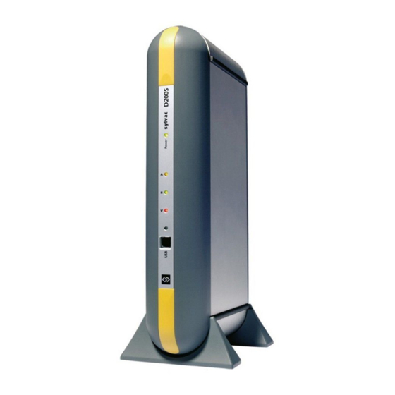
2 General description of D200S unit The D200S acquisition unit is a unit being able to read up to 8 probes Sylvac P2, P5, P10, P25, P50 with a maximum resolution of 0.1 µm and that in a dynamic mode. -
Page 5: Rear Of Unit
2.2 Rear of unit Digital output connector Socket for charging unit Socket for external contact ON / OFF Switch USB connector Probes input RS232 connector 2.3 Functions of connectors (rear panel) ON / OFF switch Pin 1 Ground Pin 2 Input + 9 V Pin 3 External contact input, signal = 0 Volt... - Page 6 Pin 1 Not used Pin 2 TXD = input RS 232 C Pin 3 RXD = output RS 232 C Pin 4 Not used Pin 5 SG = Signal ground Pin 6 Not used Not used Pin 7 Pin 8 Not used Pin 9 Not used...
- Page 7 Max voltage = 30V and the max current is 60 mA per output. The opto-coupler outputs must be supplies externally with negative voltage to common emitters (pin 6) The protection diode is necessary in case of inductive charge (electro- valve, relay, solenoid…) Pin 6 : Common for 8 opto-coupler outputs Pin 5 : Output + 5V / 100 mA , non-regulated (protected) Pin 4...
-
Page 8: Software D200S
D200S unit can only be used (without connection and software) 2. The software can be used on line with the D200S unit, which will make it possible to follow measurements to the screen, as well as the bargraph of the... -
Page 9: Installation Of Software D200S
.2 Installation of software D200S npack the CD of installation and introduce it into the CD reader of the PC. elect the CD reader directory for installation, then Setup.msi file and double click on ollow the instructions on the PC. -
Page 10: Hardware Connection Between D200S Unit And Pc
The use of an erroneous sector adapter can damage the D200S unit. 6) Connect the sector adapter to the main power. ) Switch ON the D200S unit then the 3 led's of tolerances flicker during a short moment and the PC detects the D200S unit automatically. -
Page 11: Checking Of Frontal Led Indicators
OFF theD200S unit, wait 10 seconds and switch ON the unit again. Colour Description Power green the D200S unit is connected to the sector and ready. Activities USB green Indicate that the data are received / transmitted via USB connection. -
Page 12: Connection (Software) With D200S Unit
("control panel /syste m" then select "material" and "peripheral managers "). The D200S appears as "a USB Serial Port". Each D200S connected to the PC will have a COM port which will be a llocated for it. -
Page 13: Use Of Software D200S
(* syl) pen Configuration (From D200S) his sub-menu allows you to activate the saved configuration in the D200S unit. ransfer (to D200S) his sub-menu allows you to transm it temporarily the configuration of the software in e D200S unit. -
Page 14: Sub-Menu Rs232 Setup
(for example: ever y three seconds (3000 ms) To select a second connec tion, click the appendix in white, than sele ct the second port used. Idem for use of a third D200S unit. -
Page 15: Sub-Menu Channel Setup
4.1.2 Sub-menu Channel Setup Configuration of the channels Each channel can be configured with the following parameters: Setting : Upper Tol. = Upper tolerance Lower Tol.. =Lower tolerance Nominal Value = Nominal value Preset Value = Pre-selected value Measurin g direction and mode Increase (+) = positive (+) Decrease (-) = negative (-) Measuring type: External or Internal... -
Page 16: Sub-Menu Sequences Configuration
4.1.3 Sub-menu Sequences Configuration Configuration of the measuring sequences This configuration allows the assignment of a certain number of channels to a sequence, in order to send on Excel (or other), that values introduced for a sequence given. It is possible to configure up to 8 sequences. * The use of the preset and the send are affected by the configuration of the sequences, by default only the sequence I is activated and all the... -
Page 17: Sub-Menu Foot Pedal, Switch 1 And 2 Setting
4.1.4 -menu Foot Pedal, Switch 1 and 2 Setting Single Function Allows th e attribution of a single function to the external contact Combined Function Allows the attribution of multiple functions to the external contac t. It is possible to combine up to 4 functions. -
Page 18: Sub-Menu Digital Output
4.1.5 Sub-menu Digital Output Digital Output This menu allows modif ying the configuration of the digital outputs according to 2 functionin g modes: Master Tol & D110 Channel Tol According to the con figuration, the digital Output functions will be modified according table page 79... -
Page 19: Sub-Menu Simulation Mode
4.1.6 Sub-menu "Simulat ion Mode" his menu allows the simulation of the digital outputs and the external contacts. Shows the saved file Simulates an action on the concerned contact The actions of the external contacts and the switches Activates successively the 1/2 are saved in a file frontal LED's and t hose of... -
Page 20: Sub-Menu Send To
The option "Set window on top" makes it possible to send the values in Excel/Notepad hile keeping software D200S to the foreground. T e option "Print Time & Date / Piece Number" allows sending the date, the time nd the number of the part to Excel / Notepad before sending the measured values. - Page 21 Notepad . Sele Notepad . Click on the icon Send. A Notepad file will open, as well as the Send icon Click on the icon Send, the selected values will be displayed to the Notepad file. xt File / .xls File .
-
Page 22: Sub-Menu Open File
Sub-menu Save As… Save a file The current configuration can be stored in a file (* syl) .1.10 Open Configuration (from D200S) Read the configuration o f unit D200S Allows to charge the con figuration saved in the unit D200S. -
Page 23: Transfer (To D200S)
4.1.11 Transfer (to D200S) Transfer the PC configuration in to the D200S The configuration of the PC will be transferred to D200S unit (temp orarily) * with the extinction of the unit D20 0S, the D200S will take again its basic configuration. -
Page 24: Functions Of The Basic Screen
5 Functions of the basic screen .1 Standard Mode Menu Name of Part Bargraph display Activates/deactivates the Indicator of tolerances (global) function keys Enables/ Disables Version of the connected unit the connection Value of measurement Enables / Disables Indicator of Channel n° Dynamic mode Initializes the dynamic mode... -
Page 25: Bargraph Mode
5.2 Bargraph Mode Back to Standard mode Value of measurement Tol.Low bargraph Tol.Upper mesure Ext / Int Preset Measuring mode hortcut keys (keyboard) : Min/max : Clear : Preset : Send : Save Config. : load Config. : Activates/deactivates the function keys : change Resolution : Bargraph /standard display : mm ->... -
Page 26: Example Of Measurement With Two Points Of Measurement (2 Probes)
5.3 Example of measurement with two points of measurement (2 probes) 0.005 1. Place the part between centers. Place the probe A and B i ontact with the part. 3. The configuration of channel 1 (A) will be as follows : Setting Upper Tol. - Page 27 (to D200S). The configuration will be saved until the extinction of the 200S unit. o save the current configuration definitively in the D200S unit, use the Transfer + ave (to D200S). The configuration will be saved definitively in the D200S unit.
-
Page 28: Example Of Measurement With Four Points Of Measurement (4 Probes) With
5.4 Example of measurement with four points of measurement (4 probes) with two D200S units. 0.025 F he first D200S unit covers the channels 1 t o 8. he second D200S unit covers the channels 9 to or this application we will use channels 1,2 and 9 1. - Page 29 Transfer (to D200S). The configuration will be saved until the extinction of the D200S unit. To save the current configuration definitively in the D200S unit, use the Transfer + Save (to D200S). The configuration will be saved definitively in the D200S unit.
-
Page 30: Example Of Communication With Software Winwedge 32
6 Communication protocol (remote commands) The unit can work without the software D200S. The D200S unit can receive retro- commands and thus modify the para meters of its configuration. The user can use a serial software of communication (e.g. Winwedge...) to fulfilled simple functions or to create his own software. -
Page 31: Code For Remote Commands
6.2 Code for remote comma Code Function • ? rint out of the displayed value (8 Channels.) • ?X The unit sends the value of the selected channel X : 1-8 .g. : « ?6 » the value of channel 6 will be sent) •... - Page 32 See chapter 4.1.4 • MtlX Modify the status of tolerances LED’S X : <,=,> (eg: « Mtl= » , Switch ON the green led tolerance of the D200s unit) • OutX Configure the digital output 0 : canal tol X : 0,1 1 : Master tol (eg : «...
- Page 33 • Select the measuring mode MMCX1X2X3X4X5X6X7X8 0 : direct X1, X2, .., X8 : 0 to 5 1 : max X1 configure channel 1 2 : min configure channel 2 3 : delta …. 4 : mean X8 configure channel 8 (eg : «...
-
Page 34: Calibration Of The Unit
7 Calibration of the unit The calibration of unit D200 S is made by the manufacturer. If a re-calibration is necessary, pr oceed as follo ) Fix the probe P2, P5, P10, P25 or P50 on a vertical sup port. 2) Select a resolution of 0 001 m m or 0.000... - Page 35 1 External contact, by foot-pedal USB/RS232 for remote commands from a PC. 2 External contacts on digital outputs PC Connection USB or RS232 Accuracy D200S + probes Type of probe Error average σ) Repeatability (+/- 2 1.5 µm 0.3 µm 1.6 µm...
- Page 36 304 mm 61 mm 171 mm 10 Delivery Cardboard box including: 1 unit including: Nr Designation Code N° D200S unit Charger European 230 V 904.4010 or Charger UK 240V 904.4011 or Charger USA 120V 904.4012 or Charger Japan 100V 904.4013 USB cable (3 meters) C218.058...
- Page 39 E-mail: v ente@sylvac.ch Edition 2009.02 / V1.0 / Manuel_D200S_FDE Web site: w ww.sylvac.ch 681.087-100...
Need help?
Do you have a question about the D200S and is the answer not in the manual?
Questions and answers