Table of Contents
Advertisement
Quick Links
Advertisement
Table of Contents

Summary of Contents for LeddarTech LeddarOne
- Page 1 LeddarOne UIDE...
- Page 2 Page Intentionally Left Blank...
- Page 3 Company. The Company assumes no responsibility for any errors or omissions in this document. ® Leddar is a trademark of LeddarTech Inc. All other trademarks are the property of their respective owners.
-
Page 4: Table Of Contents
Menu Bar ..........................27 4.3.2. Toolbar..........................29 4.4. Using Leddar Configurator ..................29 4.4.1. Configurating Serial Port ......................29 4.4.2. Acquisition Settings ......................31 4.4.3. Saving and Loading a Configuration ..................31 4.4.4. Configuring Detection Records ....................32 Page 4 of 52 54A0025-5 102018 © LeddarTech Inc. - Page 5 Performance ....................... 43 5.5.1. Accuracy ..........................43 5.5.2. Supply Voltage Versus Accuracy ..................44 5.5.3. Range ..........................44 5.5.4. Detection Threshold ......................45 5.6. Regulatory Compliance ....................46 5.7. Dimensions ........................ 47 Technical Support ................... 48 Index……………………………………………………………………………………49 LeddarOne – User Guide Page 5 of 52...
-
Page 6: Introduction
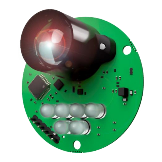
Real-time display of detection and measurement data ▪ Data recording and logging. Leddar™ Enabler SDK Complete C example demonstrating parameter configuration and data acquisition using the MODBUS protocol over the serial link. Page 6 of 52 54A0025-5 102018 © LeddarTech Inc. - Page 7 The following is a description of the main components of the Leddar™One. Figure 1: Leddar™ One Module (3° optics) LeddarOne – User Guide Page 7 of 52...
- Page 8 This is a pulled-up input that must be pulled down below 0.8 V for at least 350 ns and then released to reset the processor. The pin 1 position is shown in Figure 1. Page 8 of 52 54A0025-5 102018 © LeddarTech Inc.
- Page 9 “Waiting… (press 'a' to abort)” appears in the terminal. You can then start the YMODEM transfer of the firmware file. Once the transfer is completed, either “Successful!” or “Failed!” will appear. On success the sensor will automatically start. LeddarOne – User Guide Page 9 of 52...
- Page 10 The MCU recovers the waveforms from the FPGA, performs full waveform analysis, and generates detection and ranging data. The data can be acquired and displayed in software through the serial port. Page 10 of 52 54A0025-5 102018 © LeddarTech Inc.
-
Page 11: Underlying Principles
1.2. Underlying Principles Created by LeddarTech, LEDDAR™ (light-emitting diode detection and ranging) is a unique sensing technology based on LED illumination (in either the visible or the infrared spectrum) and the time-of-flight of light principle. The LED emitters illuminate the area of interest (pulsed at high frequency) and the single channel sensor receiver collects the backscatter of the emitted light and measures the time taken for the emitted light to return back to the sensor. -
Page 12: Signal Processing Algorithm Overview
The pulse detector analyzes the full-waveform signal in order to recognize these pulses and compute their distance. By nature, time-of-flight sensor using full-waveform analysis is able to detect several distinct objects with a single photodiode element. Page 12 of 52 54A0025-5 102018 © LeddarTech Inc. -
Page 13: Saturation Compensation
Section 5.5.2 for more details. 1.3.4. Saturation Compensation The algorithm classifies the detected pulses based on their shape. The LeddarOne determines which pulses are saturated and which have a normal shape. It is noted that other families of the products have more advanced classification technology such as merged object discrimination. -
Page 14: Getting Started
2.1. Setup To configure the sensor and see measurements the Leddar™ Configurator software must be installed. This software is available for download at www.leddartech.com/support. Once you have downloaded the file, simply double-click on it and follow on-screen instructions. Figure 5: Leddar™ Software Setup Dialog Box The installer creates an icon on the computer desktop and in the Start menu. - Page 15 Figure 6: Connecting to a Device 3. In the Connection window, select your serial port and click Connect. Figure 7: Connection Window The main window displays the detections (green bar) in the distance gauge. LeddarOne – User Guide Page 15 of 52...
-
Page 16: Measurement And Settings
The dashed lines illustrate the full-beam and the solid line indicates the distance measured by the sensor. 3.2. Data Description Measurement data can be displayed in the Raw Detections window (View menu > Raw Detections). Figure 9: Raw Detections Dialog Box Page 16 of 52 54A0025-5 102018 © LeddarTech Inc. -
Page 17: Acquisition Settings
To open the Acquisition Settings dialog box, on the Device menu, point to Configuration and click Acquisition… Figure 10: Acquisition Setting Dialog Box To apply the changes, click the apply button ( ) in the main window. LeddarOne – User Guide Page 17 of 52... - Page 18 It is recommended to set the LED intensity to a level that will provide a strong signal for the typical object and range. Note that setting the LED intensity below 100% will reduce the detection range. Page 18 of 52 54A0025-5 102018 © LeddarTech Inc.
-
Page 19: Led Intensity
−16 to 16. Select the Disabled check box or set the value at −17 to disable smoothing. Higher values increase the sensor precision but reduce the sensor reactivity. An example of the behavior of the measurement smoothing algorithm is depicted in Figure 11 below. LeddarOne – User Guide Page 19 of 52... -
Page 20: Measurement Rate
For example, with 256 accumulations and an oversampling value of 8: 72131 ���������������������� �������� = = 35.22 ���� 256 ∗ 8 Table 5 below presents the measurement rate for typical values of accumulations and oversampling. Page 20 of 52 54A0025-5 102018 © LeddarTech Inc. -
Page 21: Serial Port Settings
50 Hz. The following serial port settings are configurable. Table 6: Serial Port Setting Description Parameter Value Baud Rate 9600, 19200, 38400, 57600, 115200 bps Modbus Address 1 to 247 LeddarOne – User Guide Page 21 of 52... -
Page 22: Modbus Protocol
The full firmware version as 4 16-bit values The firmware 32-bit CRC The FPGA version Device option flags (LeddarTech internal use) Device identification code Write Configuration (function code 0x46) This function writes the current configuration registers to permanent memory. There is no data in input or output. - Page 23 3. If an error occurs while trying to execute the function, error code 4 will be returned. See Section 3.3 and 3.5 for an explanation of settings. LeddarOne – User Guide Page 23 of 52...
-
Page 24: Sdk
Windows with VisualStudio 2008 (or later) with the provided solution. It can be used in Linux with the provided Makefile (as long as development tools are installed). Page 24 of 52 54A0025-5 102018 © LeddarTech Inc. -
Page 25: Leddar Tm Configurator
In the Connection dialog box, select the serial port that you want to establish a connection with and click Connect. The device has default serial port parameters. Once connected, you can modify the baud rate or/and ModBus Address (see section 4.4.1). LeddarOne – User Guide Page 25 of 52... - Page 26 The Leddar™ Configuration main window changes to display sensor information. Figure 13: Leddar™ Configurator Main Window Page 26 of 52 54A0025-5 102018 © LeddarTech Inc.
-
Page 27: Leddar Tm Configurator Main Window
See section 3.3 for guidelines regarding low and saturated detections 4.3.1. Menu Bar This section presents, in the form of a table, the parameters and functionalities you can access through the menus and commands. LeddarOne – User Guide Page 27 of 52... - Page 28 State Save Configuration Configuration Raw Detections Load Configuration Acquisition Start Recording Communication Start Data Logging Action Quit Reset Update Calibration (only with integrator license) Settings Help Preferences User Guide Licenses About Page 28 of 52 54A0025-5 102018 © LeddarTech Inc.
-
Page 29: Toolbar
This section presents the procedures to view, configure, and analyze detections from the sensor using Leddar™ Configurator. 4.4.1. Configurating Serial Port The sensor serial port settings are configurable. To open the Communication Settings dialog box, on the Device menu, point to Configuration and click Communication. LeddarOne – User Guide Page 29 of 52... - Page 30 The numbers are modified by using the arrows or by entering the value manually. Table 11: Sensor Serial Port Setting Description Parameters Values Baud Rate Transmission rate of 9600, 19200, 38400, 57600, or 115200 bps Address Modbus device address 1 to 247 Page 30 of 52 54A0025-5 102018 © LeddarTech Inc.
-
Page 31: Acquisition Settings
On the File menu, click Load Configuration and then select a file. Once the file is selected, information on the file will be displayed and the user will be asked if this configuration can be sent to the device. LeddarOne – User Guide Page 31 of 52... -
Page 32: Configuring Detection Records
5. Under What, select the Debug check boxes if the recording is to share with LeddarTech technical support. This records additional data and results in larger log files. It is not otherwise recommended to enable this option. 6. Under How Long, next to Maximum record time, determine the length of time for a single log file by using the arrows or by entering the value manually. -
Page 33: Using Detection Records
The Start, End, and Extract buttons allow you to select a portion of the recording and extract it for further reference or analysis. To play a record: If you are connected to a device, disconnect from the device. Open another Leddar™ Configuration software main window. LeddarOne – User Guide Page 33 of 52... - Page 34 Play the record and stop it at a position of interest and then click the Start button; restart playing the record and stop it again at a position of interest and click the Stop button. Click the Extract button to extract and save that file segment. Page 34 of 52 54A0025-5 102018 © LeddarTech Inc.
-
Page 35: Data Logging
1. On the Settings menu, click Start Data Logging… Figure 23: Setting Menu 2. In the Directory dialog box, click the browse button to select the path where you want to save the log and click OK. LeddarOne – User Guide Page 35 of 52... -
Page 36: Raw Detection
To open the Raw Detections dialog box, on the View menu, click Raw Detections. Figure presents an example of raw detections. Only the detections that meet the amplitude and distance settings appear in the list. Page 36 of 52 54A0025-5 102018 © LeddarTech Inc. - Page 37 Distance and Amplitude Columns The Distance column displays the distance of the detection and the Amplitude column displays its amplitude. Flag Column The Flag column displays a number that represents a detection type. LeddarOne – User Guide Page 37 of 52...
-
Page 38: Update
Under General Leddar™One Sensing Module, some parameters of the main window can be modified. Select “Show all detections” in order to display multi-detection in the distance gauge. 4.4.10. License Manager Some features need an activation key. Contact LeddarTech for more information. Page 38 of 52 54A0025-5 102018 © LeddarTech Inc. -
Page 39: Device State
This section gives the current intensity of the LED. It is particularly useful when the device is set in automatic LED intensity, since the user can see the intensity selected by the sensor. LeddarOne – User Guide Page 39 of 52... -
Page 40: Calibration Of The Static Noise
Software: The software version of the device. Part numbers This provides the hardware and software part numbers of a device as assigned by LeddarTech 4.4.12. Calibration of the Static Noise The static noise of the sensor can be calibrated by the user. This feature is available with the integrator license available on request by contacting LeddarTech customer service. - Page 41 A progress bar will show the progression of the calibration. It should take about 1 minute to execute the calibration. The calibration can be canceled at any time by clicking on “Cancel.” LeddarOne – User Guide Page 41 of 52...
-
Page 42: Specifications
Table 14: Electrical Specifications DC supply voltage Power consumption (fully active, 100% 1.3 W LED intensity) 5.4. Optical Table 15: Optical Specifications Beam (half-angle @ 3° 50%) Wavelength 850 nm (near infrared) Page 42 of 52 54A0025-5 102018 © LeddarTech Inc. -
Page 43: Performance
Reflective Tape, 5x7 cm 0.06 Kodak White Card 90%, 20x25 cm Kodak Grey Card 18%, 20x25 cm 0.04 0.02 Reference Distance (m) Figure 32: Accuracy versus Target Reference Distance (accumulation 256 and oversampling 8) LeddarOne – User Guide Page 43 of 52... -
Page 44: Supply Voltage Versus Accuracy
Reflective Tape, 5x7 cm Kodak White Card 90%, 20x25 cm Kodak Grey Card 18%, 20x25 cm White Wall Reference Distance (m) Figure 34: Signal Amplitude versus Target Reference Distance (accumulation 256 and oversampling 8) Page 44 of 52 54A0025-5 102018 © LeddarTech Inc. -
Page 45: Detection Threshold
The multiple lines on each graph present the thresholds for a number of accumulations of 1 (top curve), 2, 4, 8, 16, 32, 64, 128, 256, 512, 1024, 2048 and 4096 (bottom curve). LeddarOne – User Guide Page 45 of 52... -
Page 46: Regulatory Compliance
A1 (2007) A2 (2010) Power Frequency Magnetic Field Continuous Field: 30A/m / 50 Hz & Immunity Pass 60 Hz IEC61000-4-8 (2009) Note: Testing results are valid for cable length less than 3 meters. Page 46 of 52 54A0025-5 102018 © LeddarTech Inc. -
Page 47: Dimensions
5.7. Dimensions Figure 36: Dimensions LeddarOne – User Guide Page 47 of 52... -
Page 48: Technical Support
Technical Support For technical inquiries, please contact LeddarTech® technical support by registering online at www.leddartech.com/support to easily: • Follow up on your requests • Find quick answers to your questions • Get valuable updates Or by contacting us at: + 1 418 653-9000 + 1 855 865-9900 8:30 a.m. -
Page 49: Index
Intensity ............18 Saving a configuration ........31 Pulse Rate ............ 42 Segment, raw detection ........37 Load, CPU ............39 Segments ............27 Loading a configuration ........31 Serial number ............40 Serial port Baud rate............21 LeddarOne – User Guide Page 49 of 52... - Page 50 Point count ............ 18 Timers & Load ...........39 Smoothing ............. 18 Static Noise Removal ........18 Signal display ............ 27 Smoothing ............18 USB port ............42 Static Noise Removal ........18 Wavelength ............42 Page 50 of 52 54A0025-5 102018 © LeddarTech Inc.
- Page 51 Page Intentionally Left Blank LeddarOne – User Guide Page 51 of 52...
- Page 52 Page 52 of 52 54A0025-5 102018 © LeddarTech Inc.