Advertisement
Quick Links
OPERATING INSTRUCTIONS
This Instruction is to be used in conjunction with the standard
Operating Instructions for YORK Model YT & YK chillers
furnished with an optional Variable Speed Drive (VSD).
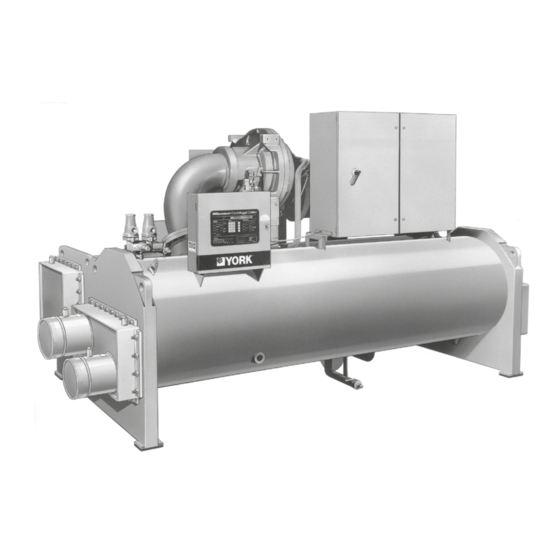
YORK MODEL YK CHILLER WITH OPTIONAL VARIABLE SPEED DRIVE
VSD Style Variations .......................................................................................... 2
VSD Unit and Harmonic Filter Component Overview ......................................... 2
VSD Control System Overview........................................................................... 7
Control Panel VSD Related Keypad Functions ................................................ 10
VSD Adaptive Capacity Control ........................................................................ 12
VSD Display Messages .................................................................................... 13
VARIABLE SPEED DRIVE
Supersedes: 160.00-O1 (702)
VSD SIZE (HP)
60 HZ
50 HZ
351
292
503
419
790
658
1100
900
TABLE OF CONTENTS
MILLENNIUM
Form 160.00-O1 (1020)
Advertisement

Subscribe to Our Youtube Channel
Related Manuals for York MILLENIUM 351-46

Summary of Contents for York MILLENIUM 351-46
-
Page 1: Table Of Contents
Form 160.00-O1 (1020) This Instruction is to be used in conjunction with the standard Operating Instructions for YORK Model YT & YK chillers furnished with an optional Variable Speed Drive (VSD). YORK MODEL YK CHILLER WITH OPTIONAL VARIABLE SPEED DRIVE... - Page 2 FORM 160.00-O1 (1020) IMPORTANT! READ BEFORE PROCEEDING! GENERAL SAFETY GUIDELINES This equipment is a relatively complicated apparatus. which it is situated, as well as severe personal injury or During rigging, installation, operation, maintenance, death to themselves and people at the site. or service, individuals may be exposed to certain com- This document is intended for use by owner-authorized ponents or conditions including, but not limited to:...
- Page 3 Planned Service Agreement that leverages real time and generalized conditions. In lieu of the tradition- and historical data, delivering performance reporting, al maintenance program, a Johnson Controls YORK corrective actions required and data enabled guidance Conditioned Based Maintenance (CBM) program can for optimal operation and lifecycle assurance.
-
Page 4: Vsd Style Variations
Variable Speed Drive 351 -46 371-01742-XXX 503 -46 371-01484-XXX The new YORK VSD is a liquid cooled, transistorized, 790 -46 371-01749-XXX PWM inverter packaged in a compact cabinet small enough to mount directly onto the chiller and directly onto Style “A” – This series applies to 503 HP only. Ground the motor. - Page 5 FORM 160.00-O1 (1020) THIS PAGE INTENTIONALLY LEFT BLANK. JOHNSON CONTROLS...
- Page 6 FORM 160.00-O1 (1020) JOHNSON CONTROLS...
- Page 7 FORM 160.00-O1 (1020) JOHNSON CONTROLS...
- Page 8 FORM 160.00-O1 (1020) to form a capacitor “bank”. In order to assure an equal sharing VSD logic board. It provides the means to sense the positive, of the voltage between the series connected capacitors and midpoint and negative connection points of the VSD’s DC link. to provide a discharge means for the capacitor bank when the A Current Transformer (3T - 5T) is included on each output VSD is powered off, “bleeder”...
- Page 9 FORM 160.00-O1 (1020) LD02726 FIG. 3A – VSD INPUT CURRENT WITHOUT FILTER LD02727 FIG. 3B – VSD INPUT CURRENT WITH FILTER JOHNSON CONTROLS...
-
Page 10: Vsd Control System Overview
FORM 160.00-O1 (1020) occur on the DC link of the filter phase bank assembly. VSD CONTROL SYSTEM OVERVIEW The “trap” filter is composed of a series of capacitors (C84-C92), inductors (4L-6L) and resistors (16RES- The VSD control system is composed of various com- 18RES). - Page 11 FORM 160.00-O1 (1020) THIS PAGE INTENTIONALLY LEFT BLANK. JOHNSON CONTROLS...
- Page 12 FORM 160.00-O1 (1020) FIG. 4 – IEEE-519 FILTER OPTION JOHNSON CONTROLS...
- Page 13 FORM 160.00-O1 (1020) LD02725 JOHNSON CONTROLS...
-
Page 14: Control Panel Vsd Related Keypad Functions
FORM 160.00-O1 (1020) CONTROL PANEL VSD RELATED The older Turbo-Modulator capacity control boards KEYPAD FUNCTIONS utilized a pre-programmed three dimensional surge sur- face map for each compressor/refrigerant combination; The following keypad functions are in addition to the whereas the new ACC board automatically generates standard keypad functions as addressed in the standard its own “Adaptive”... - Page 15 DPP = X.XX; PRV = XXX%; LWTD = XX.X; FQ = XX HZ ous YORK micropanel designs. Below is an example of four histories: • D-P/P, the ratio of the condenser pressure minus the evaporator pressure to the evaporator pressure.
-
Page 16: Vsd Adaptive Capacity Control
VSD ADAPTIVE CAPACITY CONTROL Surge is Detected - If in the process of dropping The new York VSD utilizes a different approach to speed speed and opening vanes the compressor should reduction compared to earlier variable speed products. -
Page 17: Vsd Display Messages
FORM 160.00-O1 (1020) make certain the wiring at J3 on the ACC board is by the Current Transformers on the VSD output pole properly connected per the wiring diagram in this same assemblies and the signals are sent to the VSD logic manual. - Page 18 FORM 160.00-O1 (1020) can reach 158°F. If this message does occur, make wired in series to achieve a 900 VDC capability for the certain you have an adequate level of coolant, check DC link. It is important that the voltage be shared equally to be sure the cooling pump is operating when the unit from the junction of the center or series capacitor con- is running, and check the strainer in the primary of the...
- Page 19 FORM 160.00-O1 (1020) Message: RUN RELAY FAULT Message: LOW (CONV, OR PHASE A,B,C) HEATSINK TEMP. Redundant run signals are generated by the Micropanel, A heatsink temperature sensor indicating a temperature one via wire #24 and the second via the serial communica- below 37°F will cause the unit to shut down and display tions link.
- Page 20 FORM 160.00-O1 (1020) pressing the OPTIONS key and noting the %Job the three phase input line-to-line voltage. This setpoint FLA value displayed. A zero displayed value for this is set to the peak of the sensed input line- to-line voltage parameter (and all other VSD parameters) indicates plus 32 volts, not to exceed 760 volts and varies with a serial communications link or EPROM problem.
- Page 21 - square harmonic current distortion, in percent of the regulator on the filter logic board. maximum demand load current (15 or 30 min demand)”. In the filter option supplied by York, the displayed TDD is the total RMS value of all the harmonic current supplied Message: FLTR –5 V POWER SUPPLY FLT...
- Page 22 FORM 160.00-O1 (1020) Message: FLTR LOW HEATSINK TEMP FLT Message: FLTR SERIAL RECEIVE FAULT The temperature as measured by the filter’s thermistor is a message which would occur on some early instal- (2 thermistors on 790 HP) has dropped below 37°F. lations with the IEEE-519 Filter option.
- Page 23 FORM 160.00-O1 (1020) NOTES JOHNSON CONTROLS...
- Page 24 5000 Renaissance Drive, New Freedom, Pennsylvania USA 17349 1-800-524-1330 Subject to change without notice. Printed in USA Copyright © by Johnson Controls 2020 www.johnsoncontrols.com ALL RIGHTS RESERVED Form 160.00-O1 (1020) Issue Date: October 23, 2020 Supersedes: 160.00-O1 (702)
Need help?
Do you have a question about the MILLENIUM 351-46 and is the answer not in the manual?
Questions and answers