Table of Contents
Advertisement
Available languages
Available languages
Quick Links
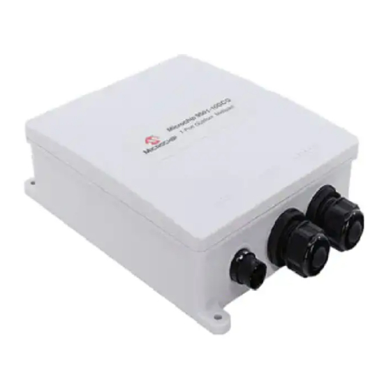
Single-port PoE Midspan User Installation Guide
Introduction
Microchip's family of PD-9501-10GCO/DC Power over Ethernet (PoE) midspan unit is a single-port high-power
PoE outdoor solution that offers a cost-effective IEEE
standard guaranteeing 60W power and ensures a safe and reliable operation in outdoor environments for standard
PoE data terminal. The PD-9501-10GCO/DC unit supports emerging wireless 10 Gbps devices such as wireless
®
IEEE
802.11ac access points.
PoE Midspans power devices that are PoE enabled or equipped to receive PoE. These devices are called power
devices (PDs).
Features
PD-9501-10GCO/DC midspan unit offers the following key features:
•
Outdoor Rated: IP66 and IP67
•
Extended Temperature Range: –40 °C to 65 °C
•
Supports 10/100/1000 Mbps and 2.5/5/10 Gbps Data Rates
•
Standards Compliant: IEEE 802.3bt and IEEE802.3af/at
•
Plug and Play Installation
•
Includes Integrated Surge Protection
©
2022 Microchip Technology Inc.
and its subsidiaries
PD-9501-10GCO/DC
®
802.3bt compliant and pre-BT support for IEEE
User Guide
®
802.3af/at
DS50003347A-page 1
Advertisement
Chapters
Table of Contents

Subscribe to Our Youtube Channel
Summary of Contents for Microchip Technology PD-9501-10GCO/DC
- Page 1 802.3bt compliant and pre-BT support for IEEE 802.3af/at standard guaranteeing 60W power and ensures a safe and reliable operation in outdoor environments for standard PoE data terminal. The PD-9501-10GCO/DC unit supports emerging wireless 10 Gbps devices such as wireless ® IEEE 802.11ac access points.
-
Page 2: Table Of Contents
Interface............................. 15 Technical Support..........................16 Revision History............................ 17 The Microchip Website..........................18 Product Change Notification Service......................18 Customer Support............................18 Microchip Devices Code Protection Feature....................18 Legal Notice..............................19 Trademarks..............................19 User Guide DS50003347A-page 2 © 2022 Microchip Technology Inc. and its subsidiaries... - Page 3 PD-9501-10GCO/DC Quality Management System........................20 Worldwide Sales and Service........................21 User Guide DS50003347A-page 3 © 2022 Microchip Technology Inc. and its subsidiaries...
-
Page 4: Standards And Safety Guidelines
GS Compliance GS marking on this product indicates that this product complies with the German Product Safety Act. Surge/Lightening Protection Microchip’s PD-9501-10GCO/DC is designed according to the following EMC requirements. • ITU-T K.21 (6 kV enhanced surge)—Port and DC Main •... -
Page 5: Safety Information
Data and Data and Power ports of the midspan are shielded RJ45 data sockets. They cannot be used as Plain Old Telephone Service (POTS) sockets. Only connect RJ45 data connectors to these sockets. • When disposing this product, follow all local laws and regulations. User Guide DS50003347A-page 5 © 2022 Microchip Technology Inc. and its subsidiaries... -
Page 6: Information En Matière De Sécurité
être utilisées comme prises de service téléphonique traditionnel. Connecter seulement des connecteurs de données RJ45 à ces prises. Le câblage Ethernet connexe doit être limité à l'intérieur de l'immeuble. • Pour disposer/jeter ce produit, suivre les lois et règlements locaux. User Guide DS50003347A-page 6 © 2022 Microchip Technology Inc. and its subsidiaries... -
Page 7: Poe Midspan Unit Installation
Quick installation guide Additional Parts The following table lists the additional parts recommended for midspan installation. Quantity Part Screwdriver Wire stripper Solid Wrench No. 27 or Adjustable Wrench User Guide DS50003347A-page 7 © 2022 Microchip Technology Inc. and its subsidiaries... -
Page 8: Midspan Unit Installation
The midspan has no ON-OFF switch, simply plug the midspan into an DC power source. • PoE midspan DC power lines must be connected to the socket-outlet that shall be installed near the equipment and be easily accessible. User Guide DS50003347A-page 8 © 2022 Microchip Technology Inc. and its subsidiaries... - Page 9 The screws are not provided with the kit. Tighten each screw until the midspan unit is securely attached to the mounting surface. Note: The dimensions in the above figure are in millimeters. User Guide DS50003347A-page 9 © 2022 Microchip Technology Inc. and its subsidiaries...
- Page 10 Pole bracket supports poles with diameters ranging from 60 mm to 200 mm (2.5 inches to 8 inches). • The unit must be installed with DATA IN, and DATA & PWR OUT ports facing down, as shown in the following figures. User Guide DS50003347A-page 10 © 2022 Microchip Technology Inc. and its subsidiaries...
-
Page 11: Installation Of Cables
The following figure shows the DC cable connection to the midspan unit. Figure 4-1. DC Cable Connection 8mm (5 /16 in) 0.5 Nm 25mm (1 in) “-“ “+“ 1.5 Nm User Guide DS50003347A-page 11 © 2022 Microchip Technology Inc. and its subsidiaries... -
Page 12: Rj45 Cable Installation
RJ45 cable to the DATA & PWR OUT port. Notes: Use cable up to 5 Gig Cat 5e and above outdoor grade. Use cable up to 10 Gig Cat 6 and above outdoor grade. User Guide DS50003347A-page 12 © 2022 Microchip Technology Inc. and its subsidiaries... -
Page 13: Data And Power Connection
Power Input (12 V to 24 V DATA IN Data In to the Ethernet (network) switch DATA & PWR OUT Data and power out to the Ethernet terminal User Guide DS50003347A-page 13 © 2022 Microchip Technology Inc. and its subsidiaries... -
Page 14: Troubleshooting
Verify that for this link you are using a standard UTP/FTP Category 5/5e/6 straight (non-crossover) cabling, with all four pairs. Verify that the Ethernet cable length is less than 100 meters from Ethernet source to the remote terminal. User Guide DS50003347A-page 14 © 2022 Microchip Technology Inc. and its subsidiaries... -
Page 15: Specifications
RJ45 female socket, with DC voltage on wire pairs: 7-8, 4-5 and 2.5Gig/5Gig/10Gig Base-T, plus 54 V and 1-2, 3-6 DC Power In 2 Pins DC power in – Positive and Negative User Guide DS50003347A-page 15 © 2022 Microchip Technology Inc. and its subsidiaries... -
Page 16: Technical Support
If you encounter problems while installing or using this product, consult the Microchip technical support team through the website or contact on the following number: USA/Canada Telephone: +1 877 480 2323 Internet: www.microchip.com/support User Guide DS50003347A-page 16 © 2022 Microchip Technology Inc. and its subsidiaries... -
Page 17: Revision History
PD-9501-10GCO/DC Revision History Revision History Revision Date Description 09/2022 Initial Revision. User Guide DS50003347A-page 17 © 2022 Microchip Technology Inc. and its subsidiaries... -
Page 18: The Microchip Website
Attempts to break Microchip’s code protection feature may be a violation of the Digital Millennium Copyright Act. If such acts allow unauthorized access to your software or other copyrighted work, you may have a right to sue for relief under that Act. User Guide DS50003347A-page 18 © 2022 Microchip Technology Inc. and its subsidiaries... -
Page 19: Legal Notice
The Adaptec logo, Frequency on Demand, Silicon Storage Technology, and Symmcom are registered trademarks of Microchip Technology Inc. in other countries. GestIC is a registered trademark of Microchip Technology Germany II GmbH & Co. KG, a subsidiary of Microchip Technology Inc., in other countries. - Page 20 PD-9501-10GCO/DC Quality Management System For information regarding Microchip’s Quality Management Systems, please visit www.microchip.com/quality. User Guide DS50003347A-page 20 © 2022 Microchip Technology Inc. and its subsidiaries...
- Page 21 Tel: 631-435-6000 Sweden - Stockholm San Jose, CA Tel: 46-8-5090-4654 Tel: 408-735-9110 UK - Wokingham Tel: 408-436-4270 Tel: 44-118-921-5800 Canada - Toronto Fax: 44-118-921-5820 Tel: 905-695-1980 Fax: 905-695-2078 User Guide DS50003347A-page 21 © 2022 Microchip Technology Inc. and its subsidiaries...
- Page 22 Vor-BT-Unterstützung für den IEEE 802.3af/at-Standard bietet, der eine Leistung von 60 W garantiert und einen sicheren und zuverlässigen Betrieb in Außenumgebungen für Standard-PoE-Datenendgeräte gewährleistet. Der PD-9501-10GCO/DC unterstützt neue drahtlose 10-Gbit/s-Geräte wie z. B. drahtlose IEEE 802.11ac Access Points. Der PoE-Midspan versorgt Geräte, die PoE-fähig oder für den Empfang von PoE ausgerüstet sind. Diese Geräte werden als Powered Devices (PDs) bezeichnet.
- Page 23 The Microchip Website..........................18 Product Change Notification Service....................18 Customer Support..........................18 Microchip Devices Code Protection Feature..................18 Legal Notice............................18 Trademarks............................19 Quality Management System........................ 20 Worldwide Sales and Service........................21 User Guide DS50003347A-page 2 © 2022 Microchip Technology Inc. and its subsidiaries...
-
Page 24: Normen Und Sicherheitsrichtlinien
GS-Übereinstimmung Das GS-Zeichen auf diesem Produkt bedeutet, dass das Produkt dem deutschen Produktsicherheitsgesetz entspricht. Überspannungs-/Blitzschutz Der PD-9501-10GCO/DC von Microchip wurde gemäß den folgenden EMC-Anforderungen entwickelt. • ITU-T K.21 (6 kV erweiterte Überspannung)—Port und DC-Hauptschalter • EN61000-4-5 (6 kV)—Port und DC-Hauptschalter •... -
Page 25: Sicherheitshinweise
Plain Old Telephone Service (POTS)-Buchsen verwendet werden. Schließen Sie nur RJ45- Datenstecker an diese Buchsen an. • Beachten Sie bei der Entsorgung dieses Produkts alle örtlichen Gesetze und Vorschriften. User Guide DS50003347A-page 4 © 2022 Microchip Technology Inc. and its subsidiaries... -
Page 26: Information En Matière De Sécurité
être utilisées comme prises de service téléphonique traditionnel. Connecter seulement des connecteurs de données RJ45 à ces prises. Le câblage Ethernet connexe doit être limité à l'intérieur de l'immeuble. • Pour disposer/jeter ce produit, suivre les lois et règlements locaux. User Guide DS50003347A-page 5 © 2022 Microchip Technology Inc. and its subsidiaries... -
Page 27: Installation Des Poe Midspan-Geräts
Kurzanleitung zur Montage Zusätzliche Teile In der folgenden Tabelle finden Sie die für die Montage des Midspan empfohlenen zusätzlichen Teile. Menge Teil Schraubendreher Abisolierzange Schraubenschlüssel Nr. 27 oder verstellbarer Schraubenschlüssel User Guide DS50003347A-page 6 © 2022 Microchip Technology Inc. and its subsidiaries... -
Page 28: Installation Des Midspan-Geräts
Der Midspan hat keinen EIN/AUS-Schalter, schließen Sie den Midspan einfach an eine DC-Stromquelle an. • PoE-Midspan-DC-Stromleitungen sollten an eine Steckdose angeschlossen werden, die in der Nähe des Geräts montiert und leicht zugänglich sein sollte. User Guide DS50003347A-page 7 © 2022 Microchip Technology Inc. and its subsidiaries... - Page 29 Die Schrauben sind nicht im Lieferumfang des Kits enthalten. Ziehen Sie jede Schraube an, bis der Midspan sicher an der Montageoberfläche befestigt ist. Anmerkung: Die Abmessungen in der obigen Abbildung sind in Millimeter angegeben. User Guide DS50003347A-page 8 © 2022 Microchip Technology Inc. and its subsidiaries...
- Page 30 Das Gerät muss so installiert werden, dass die Dateneingangs- und Datenausgangs- sowie Stromausgangs-Ports (DATA IN und DATA & PWR OUT) nach unten zeigen, wie in den folgenden Abbildungen dargestellt. User Guide DS50003347A-page 9 © 2022 Microchip Technology Inc. and its subsidiaries...
- Page 31 PD-9501-10GCO/DC Installation des PoE Midspan-Geräts User Guide DS50003347A-page 10 © 2022 Microchip Technology Inc. and its subsidiaries...
-
Page 32: Installation Der Kabel
Zugelassen für Anwendungen im Innen- und Außenbereich. Die folgende Abbildung zeigt den Anschluss des DC-Netzkabels an das Midspan-Gerät. Abbildung 4-1. DC-Netzkabelanschluss 8mm (5 /16 in) 0.5 Nm 25mm (1 in) “-“ “+“ 1.5 Nm User Guide DS50003347A-page 11 © 2022 Microchip Technology Inc. and its subsidiaries... -
Page 33: Rj45-Netzkabelinstallation
Verwenden Sie Kabel bis zu 5 Gig Cat 5e und darüber für den Außenbereich. Verwenden Sie Kabel bis zu 10 Gig Cat 6 und darüber für den Außenbereich. User Guide DS50003347A-page 12 © 2022 Microchip Technology Inc. and its subsidiaries... -
Page 34: Daten- Und Stromanschluss
Schutzklassen IP66 und IP67 entspricht. Etikett Beschreibung LINE IN Netzeingang( 12 V bis 24 V DATA IN Dateneingang zum Ethernet (Netzwerk)-Switch DATA & PWR OUT Daten- und Stromausgang zum Ethernet-Terminal User Guide DS50003347A-page 13 © 2022 Microchip Technology Inc. and its subsidiaries... -
Page 35: Fehlersuche
Standard-UTP/FTP-Kabel der Kategorie 5/5e/6 mit allen vier Paaren verwenden. Stellen Sie sicher, dass die Länge des Ethernet-Kabels von der Ethernet- Quelle zum Remote-Endgerät weniger als 100 Meter beträgt. User Guide DS50003347A-page 14 © 2022 Microchip Technology Inc. and its subsidiaries... -
Page 36: Technische Daten
RJ45-Buchse, mit DC-Spannung auf Adernpaaren: 7 - 8, 4 - und 2.5Gig/ 5Gig/10Gig Base-T plus 54 V 5 und 1 - 2, 3 - 6 DC-Stromeingang (DC Power In) 2 Pins DC-Stromeingang Positiv und Negativ User Guide DS50003347A-page 15 © 2022 Microchip Technology Inc. and its subsidiaries... -
Page 37: Technischer Support
Sollten bei der Installation oder Verwendung dieses Produkts Probleme auftreten, wenden Sie sich an den technischen Support von Microchip über die Webseite oder unter der folgenden Nummer: USA/Kanada Telefon: +1 877 480 2323 Internet: www.microchip.com/support User Guide DS50003347A-page 16 © 2022 Microchip Technology Inc. and its subsidiaries... -
Page 38: Überarbeitungsübersicht
PD-9501-10GCO/DC Überarbeitungsübersicht Überarbeitungsübersicht Überarbeitung Datum Beschreibung 09/2022 Erste Überarbeitung. User Guide DS50003347A-page 17 © 2022 Microchip Technology Inc. and its subsidiaries... -
Page 39: Informationen Zu Microchip
Microchip products with your application. Use of this information in any other manner violates these terms. Information regarding device applications is provided only for your convenience and may be superseded User Guide DS50003347A-page 18 © 2022 Microchip Technology Inc. and its subsidiaries... -
Page 40: Trademarks
The Adaptec logo, Frequency on Demand, Silicon Storage Technology, Symmcom, and Trusted Time are registered trademarks of Microchip Technology Inc. in other countries. GestIC is a registered trademark of Microchip Technology Germany II GmbH & Co. KG, a subsidiary of Microchip Technology Inc., in other countries. -
Page 41: Quality Management System
PD-9501-10GCO/DC Quality Management System For information regarding Microchip’s Quality Management Systems, please visit www.microchip.com/quality. User Guide DS50003347A-page 20 © 2022 Microchip Technology Inc. and its subsidiaries... -
Page 42: Worldwide Sales And Service
Tel: 631-435-6000 Sweden - Stockholm San Jose, CA Tel: 46-8-5090-4654 Tel: 408-735-9110 UK - Wokingham Tel: 408-436-4270 Tel: 44-118-921-5800 Canada - Toronto Fax: 44-118-921-5820 Tel: 905-695-1980 Fax: 905-695-2078 User Guide DS50003347A-page 21 © 2022 Microchip Technology Inc. and its subsidiaries...
Need help?
Do you have a question about the PD-9501-10GCO/DC and is the answer not in the manual?
Questions and answers