
Subscribe to Our Youtube Channel
Related Manuals for Koei Industry Nucom Series

Summary of Contents for Koei Industry Nucom Series
- Page 1 ACT-N02E-1 ELECTRONIC CONTROL ACTUATOR “ Nucom Series “ ROTARY TYPE Nucom-10NS Nucom-10NM Nucom-10NL Nucom-10NL-100 Nucom-10NL-150 Nucom-10NL-200 OPERATION MANUAL Koei Industry Co., Ltd.
- Page 2 ACT-N02E-1 FOR YOUR SAFETY In order for better and safety use of the product for a long period, please observe this “ WARNING and CAUTION “ carefully. Here are the specification and operation manual for the product to prevent suffering injury or loss by accidents.
-
Page 3: Table Of Contents
ACT-N02E-1 CONTENTS 1. GENERAL 2. CONFIGURATION 2-1 Configuration and names of parts 2-2 Dimensions 3. SPECIFICATION 4. OPERATION PRINCIPLE 4-1 Operation principle 4-2 Block diagram 5. INSTALLATION 6. WIRING 6-1 Cables 6-2 Water prevention 7. ASSEMBLY WITH A VALVE 7-1 Names of parts 7-2 Assembly procedures 8. -
Page 4: General
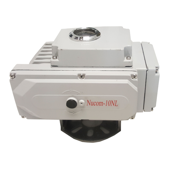
ACT-N02E-1 1.GENERAL This is a quarter turn electronic control actuator series. The modulated actuators are operated with 4~20mA DC(or 1~5V DC) direct signals from a computer. The precision (control resolution) of 1/250 is far higher than those of conventional pneumatic systems. FEATURES 1. - Page 5 ACT-N02E-1 2-2 Nucom-10NS, 10NM, 10NL external drawings <Nucom-10NS> <Nucom-10NM>...
- Page 6 ACT-N02E-1 <Nucom-10NL, -100, -150, -200>...
-
Page 7: Specification
ACT-N02E-1 3. FUNCTIONAL SPECIFICATION Nucom-10NS Nucom-10NM MODEL ITEM SPECIAL SPECIAL AC100·110·115·120V ± 10% (50/60 Hz) RATED POWER AC200·220·230·240V ± 10% (50/60 Hz) 4~20mA·DC (Standard Specification) INPUT SIGNAL 4~12/12~20mA·DC (Optional Specification) 49N·m 98 N·m 196N·m 392 N·m OUTPUT TORQUE (5kgf·m) (10 kgf·m) (20kgf·m) (40 kgf·m) 15sec(50HZ) - Page 8 ACT-N02E-1 Nucom- MODEL ITEM 10NL 10NL-100 10NL-150 10NL-200 AC110·115·120V ± 10% (50/60 Hz) RATED POWER AC220·230·240V ± 10% (50/60 Hz) 4~20mA DC (Standard Specification) INPUT SIGNAL 4~12/12~20mA DC (Optional Specification) 490N·m 980N·m 1470N·m 1960N·m OUTPUT TORQUE (50kgf·m) (100kgf·m) (150kgf·m) (200kgf·m) 15sec 30sec 45sec...
-
Page 9: Operation Principle
ACT-N02E-1 4. OPERATION PRINCIPLE 4-1 Operation principle The system makes computation between input signals (4~20mA DC) and position signals, then turns the motor in direction to balance them, and stops the motor when they are balanced. The motor torque is transmitted through the worm structure to the actuator shaft. Rotation direction (direct or reverse) is selectable at the setting switch. -
Page 10: Installation
ACT-N02E-1 CAUTION ON ENVIRONMENTAL INSTALLATION CONDITIONS 5.INSTALLATION 5-1 Installation Cautions on indoor installation *Avoid a hazardous place, as this is not an explosion-proof type. *Cover whole the unit, when installing the unit in a place with water or material splashes. * It is recommendable to reserve a space for manual maintenance work. -
Page 11: Wiring
ACT-N02E-1 CAUTION ON WIRING WORK 6. WIRING 6-1 Cables Power cable Use a Φ9~11mm (outside diameter) cable for the standard resin connector. (See FIG.6) For customer connectors, use a proper size cable to match the connector preventing water ingress to the unit. Signal cable Use a sealed cable for signal wiring. -
Page 12: Assembly With A Valve
ACT-N02E-1 CAUTION ON ASSEMBLY WITH A VALVE 7. ASSEMBLY WITH A VALVE 7-1 Names of parts The actuator is removable from a valve, so that it is very easy to replace either part in case of trouble. 7-2 Assembly procedure A : For a valve that does not have a mechanical stop on close side A-1. -
Page 13: Power And Signals
ACT-N02E-1 B-2. Position the actuator at 0 % (full close), and set the actuator limit switch so as to work at 0 %. (Note that the limit switch should normally be set to work at a half turn of manual handle past the full close of signal rate.) (See FIG.9) B-3. -
Page 14: Wiring Diagram
ACT-N02E-1 8-4 Wiring diagram... -
Page 15: Control Pack (Module)
ACT-N02E-1 CAUTION 9. CONTROL PACK 9-1 Names of parts (Note) The packs with green labels or with Serial No, “SP0000” marked on the side are fitted with an exterior type 250 Ω resister, and no need to be connected. Take special care when wiring actuator. AC connectors are in the middle of terminal strip. 9-2 Direction mode Either direct or reverse action is selectable at this switch. -
Page 16: Sensitivity Volume
ACT-N02E-1 9-3 Selection of a mode during signal interruption A mode among open/stop/close is selectable at this switch in case of signal interruption. Select switch 1 = Open action Select switch 2 = Stop action Select switch 3 = Close action Setting of direction (DA/RA) and mode in signal interruption are available in 6 combinations as shown in FIG.14. -
Page 17: Operation
ACT-N02E-1 9-5 ZERO/SPAN Setting * ZERO volume CW = To increase (to OPEN direction) Adjustable range - 25 ~ +25 % * SPAN volume CW = To increase (to OPEN direction) - 50 ~ +200 % Adjustable range *Zero/Span volumes are appropriately adjusted before shipment. Do not adjust it after shipment unless imperatively required. -
Page 18: Power Operation
ACT-N02E-1 Confirm that power is OFF before making power operation 10-2 Power operation 1. Before starting power operation, check the following if they are appropriate. * Installation conditions * Ambient temperature and fluid temperature * Engagement with valve * Positions at full close and full open * Wiring * Water prevention at conduit tube * Voltage and input signals (check against specification sheet) -
Page 19: Adjustment
ACT-N02E-1 11. ADJUSTMENT 11-1 Potentiometer and limit switches 1. Position the Valve position indicator at 50 % manually, and the shaft will come to the position as shown in FIG.19. (See that the shaft is parallel with the actuator bottom) 2. -
Page 20: Mechanical Stop
ACT-N02E-1 11-2 Mechanical stop 1. Referring to Fig.21, adjust the mechanical stops with the stops’ bolts and nuts as follows. Set the limit switches functional points at a half turn with handle past input signal OP/CL positions. Set the mechanical stop positions at a half turn with handle past limit switches functional points. 2. -
Page 21: Optional Extras
ACT-N02E-1 12. TROUBLE SHOOTING TROUBLE AND PROBABLE CAUSE SOLUTION Motor does not start up Power failed or dropped Check and supply power Signal failed or dropped Check and input signals Wire broken or disconnected Change the wire or re-connect the terminal Lower the ambient temperature or decrease Thermal protector functioned duty rate.
Need help?
Do you have a question about the Nucom Series and is the answer not in the manual?
Questions and answers
can you remove the square shaft and reposition it