Table of Contents
Advertisement
Quick Links
Advertisement
Table of Contents

Summary of Contents for Interpump Hydralok H50-6ECO
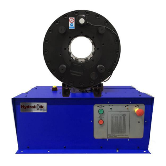
- Page 1 USER MANUAL Swaging Machine H50-6ECO...
-
Page 2: Table Of Contents
CONTENTS WARRANTY CONDITIONS ....................3 DECLARATION OF CONFORMITY ..................4 SAFETY REGULATIONS ....................5 TECHNICAL / DIMENSIONAL DATA .................. 6 HANDLING/TRANSPORT ....................6 INSTALLATION ........................6 PRELIMINARY CHECK ....................... 6 LIGHTING ..........................7 ROUTINE MAINTENANCE ....................7 MACHINE DESCRIPTION & OPERATING INSTRUCTIONS ..........8 OPERATIVE INSTRUCTIONS .................... -
Page 3: Warranty Conditions
WARRANTY CONDITIONS 1. Note that all machines undergo strict testing before shipment. 2. All machines are warranted against any defects for a period of 12 MONTHS starting from the date of delivery to the customer. The company reserves the right to require a copy of the sales invoice. -
Page 4: Declaration Of Conformity
DECLARATION OF CONFORMITY (according to current EC legislation) the subscribed: I.M.M. Hydraulics S.p.A. registered office in: Via Italia 49, 51 66041 ATESSA VAT and fiscal Code 01427010697 in the person of Marcello Di Campli declares: Model: H50-6ECO Construction Year: Serial Number: Description: Electric Round head swaging machine The machine is not included in the list of the Annex IV of Machinery Directive 2006/42/CE. -
Page 5: Safety Regulations
SAFETY REGULATIONS Always work in safe conditions and with the necessary space around the machine. Ensure that the machine is placed on a stable and appropriate working surface. 1. DO NOT USE the equipment before reading the user manual. 2. CAUTION! If improperly used, the equipment may be dangerous and may cause injury. -
Page 6: Technical / Dimensional Data
TECHNICAL / DIMENSIONAL DATA TECHNICAL/DIMENSIONAL DATA H50-6ECO 3/16” - 2” R13/4SH (6 wire) Capacity Motor [Kw] Dimensions [mm] 750x453x795 Gross weight [kg] Volts 220/240V-1ph-50/60 Hz 380/440V-3ph-50/60 Hz Max Swage [kN/tons] 4500/450 Noise level < 75 dB (A) HANDLING/TRANSPORT The machine will normally be shipped bolted to a wooden pallet. The bolts should be removed and the machine lifted onto the work place using suitable lifting equipment. -
Page 7: Lighting
LIGHTING The equipment does not have its own lighting and so it must be used in a suitably illuminated area. ROUTINE MAINTENANCE Ensure that moving parts are always lightly greased. Where applicable check periodically that the limit switches and emergency controls are in good working order. -
Page 8: Machine Description & Operating Instructions
MACHINE DESCRIPTION & OPERATING INSTRUCTIONS A bench mounted annular eight-segment hose assembly swaging machine with interchangeable dies. OPERATIVE INSTRUCTIONS When operating the machine for the first time check that the motor rotation direction is correct. (Three phase machines only) If the jaws of the swaging head do not begin to close when the green button is pressed the phase rotation of the motor will have to be reversed. -
Page 10: Die Fitting Instructions
DIE FITTING INSTRUCTIONS To Insert or remove the dies, the head must be closed. The dies are inserted from the front of the swaging head. The die holders have a T slot with a spring-loaded ball bearing to retain the die in place. Ensure that the die is fully inserted in the T slot and that the longest portion of the die from the pin is to the back of the head as shown in the next figure: Fig.2 QUICK CHANGE... - Page 11 8. Replace die tool back into its holder. 9. You are now ready to complete a swage. Note: Quick change tool must be removed from dies BEFORE dies are opened. Removing dies from the machine 1. Set calibrator to quick change setting. With the machine set on manual press the green, swage, button and close dies until they reach the required setting.
-
Page 12: Calibrator Diagram
CALIBRATOR DIAGRAM Fig.3 DIE SET TABLE Die set Crimping Length Ferrule Die set Crimping Length Ferrule Max Range Range diameter (mm) diameter (mm) (mm) (mm) 06.0 - 07.9 40.00 18.00 34.0 - 39.9 70.00 46.00 08.0 - 09.9 40.00 20.00 40.0 - 45.9 85.00 52.00... -
Page 13: Maintenance And Service
MAINTENANCE AND SERVICE A monthly check on the oil level should be carried out, more often for machines in regular use. The sliding surfaces of the head must be regularly lubricated with a molybdenum disulphide-based spray. A light spray of the surfaces each day should be sufficient but for machines operating continuously or in hot climates it may require more frequent applications. -
Page 14: Spare Parts
SPARE PARTS Part No. Description 300-108 Seal kit 300-107 Spring kit YA1004 Calibrator kit... -
Page 15: Swaging Head Drawing
SWAGING HEAD DRAWING... -
Page 16: Electrical Diagram
ELECTRICAL DIAGRAM...
Need help?
Do you have a question about the Hydralok H50-6ECO and is the answer not in the manual?
Questions and answers