Table of Contents
Advertisement
Quick Links
For products in USA:
Humanitarian Device. Authorized by Federal law for use in the treatment of pediatric patients
with severe isolated left ventricular or biventricular dysfunction who are candidates for cardiac
transplant and require circulatory support. The effectiveness of this device for this use has not
been demonstrated.
1000721x09 Revision 8
®
EXCOR
Pediatric VAD
Ventricular Assist Device
with
Stationary Driving Unit Ikus Rev. 2.1
Instructions for Use 1000721x09 Revision 8
Advertisement
Table of Contents

Related Manuals for Berlin Heart EXCOR Pediatric VAD

Summary of Contents for Berlin Heart EXCOR Pediatric VAD
- Page 1 ® EXCOR Pediatric VAD Ventricular Assist Device with Stationary Driving Unit Ikus Rev. 2.1 Instructions for Use 1000721x09 Revision 8 For products in USA: Humanitarian Device. Authorized by Federal law for use in the treatment of pediatric patients with severe isolated left ventricular or biventricular dysfunction who are candidates for cardiac transplant and require circulatory support.
- Page 2 This page was left blank intentionally 1000721x09 Revision 8...
- Page 3 Berlin Heart GmbH. Excluded are the sample co pies contained in this instruction for use.
- Page 4 This page was left blank intentionally 1000721x09 Revision 8...
-
Page 5: Table Of Contents
Content Content Dear readers, Important safety information Warnings ..........................3 1.1.1 Storage and durability ....................4 1.1.2 Transport within the clinic ....................4 1.1.3 Device configurations ....................5 1.1.4 Procedural techniques - Ikus ..................5 1.1.5 Packaging and sterilization.................... 7 1.1.6 Procedural techniques - pumps, cannulae, accessories .......... - Page 6 Content 3.6.7 Conclusion ........................47 Post Approval Study Summary..................48 3.7.1 Study Objective ......................48 3.7.2 Study Design ....................... 48 3.7.3 Study Population ......................48 3.7.4 Data source ......................... 49 3.7.5 Key Study Endpoints ....................49 3.7.6 Total number of Enrolled Study Sites and Subjects, Follow-up Rate ......49 3.7.7 Study visits and length of follow-up ................
- Page 7 Content Changing over from univentricular to biventricular operation ........... 82 6.5.1 Routine start-test when not in operation ..............83 Moving the Ikus ........................ 84 Transportation and packaging ..................84 6.7.1 Unloading the Ikus from the shipping crate ..............85 6.7.2 Loading the Ikus into the shipping crate ..............
- Page 8 Content Connecting the blood pumps to the cannulae ..............128 9.10 Removing the de-airing needle..................130 9.11 Securing the connections ....................130 Implantation - anesthesia 133 Wound care and treatment 135 11.1 Removing the old dressings ................... 136 11.2 Cleaning the blood pump....................137 11.3 Cleaning of the wound ....................
- Page 9 Content Error Messages and corrective measures 171 14.1 Pressure error / time error in system 1 (or in system 2 or 3) .......... 173 14.2 Throttle valve error in system 1 (or system 2 or 3) ............173 14.3 Please connect driving tube ................... 174 14.3.1 Replacing a driving tube ....................
- Page 10 Content 16.1.3 LV apex cannulae ...................... 212 16.1.4 Atrial cannulae......................212 16.1.5 Arterial cannulae ....................... 212 16.1.6 Overview: Which cannulae should be used for which pump? ........214 16.1.7 System accessories....................215 16.1.8 Driving unit ........................ 215 16.1.9 Special components ....................215 16.1.10 Maximum rates for the pump-cannula combinations ..........
-
Page 11: Dear Readers
® Pediatric VAD. Additionally, urgent clinical and technical assistance is available via the Berlin Heart Emergency Hotline. You can reach us 24 hours per day, 365 days per year at 866-249-0128. Always make sure that only professional medical personnel who have been specifically trained in the use of the product are permitted to work with EXCOR. - Page 12 Chapter Dear readers, Term definitions Product life How long the product can be used. No maintenance or repairs are performed after this date. With unsterile products, the product life starts on the day of (initial) shipment; with sterile products it starts on the day of implantation. All sterile products are for single use only.
-
Page 13: Important Safety Information Warnings
Only qualified medical personnel trained specifically in the use of the system are permitted to work with EXCOR. Training courses can be arranged with Berlin Heart, Inc. Use by untrained personnel can pose a risk to the patient and the EXCOR. -
Page 14: Storage And Durability
Chapter 1 Important safety information 1.1.1 Storage and durability WARNING The expiration date of each EXCOR product is found on the product labels located on both the outer and inner packaging. The pumps, cannulae and accessories must not be used after the expiration date and even not be re-sterilized. -
Page 15: Device Configurations
Otherwise there is a risk of functional limitation and/or damage to the Ikus. Failure to observe this stipulation will invalidate all warranty agreements by Berlin Heart Inc.. The connection between the connector External alarm (Nurse call) and the internal alarm system of the clinic is not failsafe. The use of this feature does not release the user from supervising the Ikus and the displayed messages and alarms. - Page 16 Chapter 1 Important safety information Only connect the mains cable of the Ikus driving unit to grounded mains power outlets.The supply voltage has to conform to the voltage requirements indicated on the Ikus identification plate. Only connect the mains cable of the Ikus driving unit to suitable power outlets complying with the electrical safety regulations of the country in which it is being used.
-
Page 17: Packaging And Sterilization
Chapter 1 Important safety information Only disconnect the Ikus from the mains if the charge level indicator shows that the batteries are completely charged (all yellow LEDs are lit). IMPORTANT: In order to prevent rapid and premature ageing of the batteries, the Ikus must always be run on the mains for at least 6 hours after using the battery operation. -
Page 18: Procedural Techniques - Pumps, Cannulae, Accessories
EXCOR sterile components may not be resterilized by the user. Any opened product must be used or sent back to Berlin Heart. If product expires please contact Berlin Heart for exchange. - Page 19 Chapter 1 Important safety information In order to prevent infection, use strict aseptic techniques during implantation and exercise extreme caution throughout the period of EXCOR cardiac support. Danger of infection! The distal end of the cannulae can be trimmed. At least 5 cm (2 inches) of material without polyester velour covering should remain to allow visual inspection of the cannula/ titanium-connector junction.
- Page 20 Chapter 1 Important safety information Do not combine the connecting set with staged cannulae in such a way that multiple diameters are bridged. Otherwise, the pump will not fill or empty completely. Secure each of the connections with at least 1 cable tie. Otherwise, the connections may loosen over time and the cannula extension set / the connecting set may become separated from the blood pump.
- Page 21 Chapter 1 Important safety information When positioning the driving tubes mitigate the risk of adverse tubing and line incidents by routing the driving tubes in a clear pattern toward the feet and to the side. Do not initiate cardiac support with the EXCOR blood pumps until the blood pumps have been completely de-aired.
-
Page 22: System
Chapter 1 Important safety information Weaning: If the patient does not meet the eligibility criteria at any time during the weaning process: Resume pumping at rate prior to any weaning (initial rate, IR). 1.1.7 System WARNING If a non-matching pump-cannula-combination (see section 16.1.10: Maximum rates for the pump-cannula combinations, page 216) was chosen, use only the connector sets provided with the system in order to minimize the risk of clots at the junctions. -
Page 23: Procedures To Minimize Risk Of Thrombosis
Chapter 1 Important safety information If the Ikus is operating in emergency pulse mode, immediately visually check whether the blood pump(s) is (are) filling and ejecting completely. If one pump is not filling and/or ejecting completely, the patient must be supported immediately using the manual pump (see section 15.5: Driving blood pump(s) with the manual pump, page 204). -
Page 24: Maintenance
If the ambient temperature is continuously above +30°C during operation, the maintenance interval or life of the batteries is reduced. The Ikus shall only be serviced by Berlin Heart GmbH/ Berlin Heart, Inc. or those authorized by Berlin Heart GmbH. For this reason, this document does not contain any circuit or wiring diagrams. - Page 25 Chapter 1 Important safety information If a message with the content ... Contact (customer) service (now)! is displayed in the message field on the laptop, replace the Ikus immediately (see chapter 14: Error Messages and corrective measures, page 171). If the emergency pulse mode is activated while the backup system is already active, the Ikus is no longer able to drive both pumps.
-
Page 26: Replacing The Blood Pump(S)
Chapter 1 Important safety information 1.1.12 Replacing the blood pump(s) WARNING When replacing a blood pump, follow the instruction given here. Otherwise the duration of the pump stop will be prolonged and the patient might suffer from inadequate support. The blood pump may only be replaced under sterile conditions! When connecting the blood pump(s), pay attention to the direction of the arrows on the inflow and outflow stubs! These show the direction of the blood flow. -
Page 27: Ambient Conditions
Chapter 1 Important safety information When operating the manual pump with 1 hand, do not block the valves with your feet (see valve "2" in Fig. 15-2, page 205). 1.1.14 Ambient conditions WARNING Protect the Ikus from exposure to moisture and wetness. Never store or operate the Ikus in a damp environment (e.g. -
Page 28: Precautions
Chapter 1 Important safety information EXCOR patients with prosthetic aortic valves may have increased risk of thromboembolism. If EXCOR is used in interaction with other procedures and therapies, observe the movement of the membrane to determine whether the blood pump is filling and ejecting completely. If a pump is not filling and/ or ejecting completely, stop the interacting procedure or therapy and institute the appropriate corrective action. -
Page 29: Ambient Conditions
Chapter 1 Important safety information The titanium connectors of the blood pumps have sharp edges designed to minimise the risk of clot formation at the junction. Be careful to avoid cutting yourself while connecting the pump and the cannulae. 1.2.2 Ambient conditions CAUTION The Ikus is intended solely for use in a hospital setting. -
Page 30: Transport Outside The Clinic
Also refer to section 6.7: Transportation and packaging, page 84. 1.2.5 Battery replacement and disposal CAUTION Only Berlin Heart GmbH/ Berlin Heart, Inc. service staff or persons authorized by the Berlin Heart GmbH service department may replace the batteries and dispose of them in accordance with the respective regulations. -
Page 31: General Information
Chapter 2 General Information General Information Device description EXCOR is an extracorporeal, pneumatically driven ventricular assist device. It is designed to support the right and/or left ventricle when the native heart is unable to maintain normal blood flows and pressures even with help of drug therapy and intra aortic balloon counterpulsation. -
Page 32: Contraindications
Chapter 2 General Information Contraindications Patients unable to tolerate systemic anticoagulation therapy should not be implanted. Magnetic Resonance Imaging (MRI) is contraindicated in patients after being implanted with the EXCOR. Patients with aortic valve regurgitation that is more than moderate that cannot be repaired at the time of implantation should not be implanted with the EXCOR. -
Page 33: Battery Replacement And Disposal
The warranty is no longer valid, if the Ikus has been opened or serviced by persons who are not members of the Berlin Heart GmbH/ Berlin Heart, Inc. service staff and/ or who have not been authorized by the Berlin Heart GmbH service department to do If an ambient temperature of +30°C is continuously exceeded during ongoing... - Page 34 Chapter 2 General Information Components Product life Maintenance Expiration Warranty interval date (in sterile products starting from implantation) Cannulae no limitation 3 years 1 year (single-use product) Accessories single-use 3 years first use product Tab. 2-1 Product life, maintenance interval, expiration date, warranty Please dispose components according to local regulations and site policies.
-
Page 35: Summary Of Clinical Studies
Chapter 3 Summary of Clinical Studies Summary of Clinical Studies Indications for use EXCOR® Pediatric Ventricular Assist Device (referred to as EXCOR) is intended to provide mechanical circulatory support as a bridge to cardiac transplantation for pediatric patients. Pediatric candidates with severe isolated left ventricular or biventricular dysfunction who are candidates for cardiac transplant and require circulatory support may be treated using the EXCOR. - Page 36 Chapter 3 Summary of Clinical Studies Ta b . 3 -1 Serious adverse event summary per cohort 1000721x09 Revision 8...
- Page 37 Chapter 3 Summary of Clinical Studies Ta b . 3 -2 Serious adverse event summary per cohort (table continued) 1000721x09 Revision 8...
-
Page 38: Ide Clinical Study
3.6.1 IDE Clinical Study Summary Berlin Heart Inc. conducted a prospective, multi-center, single arm study to assess the safety and probable benefit of the EXCOR. The purpose of the study was to determine whether use of the EXCOR for bridge-to ... -
Page 39: Inclusion/Exclusion Criteria
Chapter 3 Summary of Clinical Studies who met critical eligibility criteria. The dataset for the ELSO registry included baseline and outcomes data comparable to the EXCOR dataset. The control group was then created by matching the EXCOR subjects to the patients in the subset using a propensity score analysis (PSA). -
Page 40: Study Enrollment
Chapter 3 Summary of Clinical Studies Exclusion Criteria 1. Support on ECMO for ≥ 10 days 2. Cardiopulmonary resuscitation (CPR) duration ≥ 30 minutes within 48 hours prior to device implantation 3. Body weight < 3.0 kg or BSA > 1.5 m 4. Presence of mechanical aortic valve 5. Unfavorable or technically-challenging cardiac anatomy including single ventricle lesions, complex heterotaxy, and restrictive cardiomyopathy... - Page 41 Chapter 3 Summary of Clinical Studies ) enrolled and 53 larger sized subjects (BSA ≥ 0.7 smaller sized subjects (BSA < 0.7m to <1.5 m ) enrolled. Ta b . 3 -4 Subject enrollment Note: Enrollment in Cohorts 1 CAP, 3A, 3B (IDE and non-IDE) are supportive data and are included only in the safety summary tables.
-
Page 42: Subject Demographics
Chapter 3 Summary of Clinical Studies Fig. 3-1 Study enrollment and outcome Enrollment in Cohorts 1 CAP, 3A, 3B (IDE and non-IDE) are supportive data and are only included in the safety summary tables. 3.6.5 Subject Demographics The following table summarizes the demographic data for Cohorts 1 and 2. Males comprised the majority of the subjects in Cohort 2 (54%) and half (50%) of Cohort 1. - Page 43 Chapter 3 Summary of Clinical Studies Ta b . 3 -5 Demographic data summary (a) 1000721x09 Revision 8...
- Page 44 Chapter 3 Summary of Clinical Studies Ta b . 3 -6 Demographic data summary (b) Pre-implant support for the subjects is detailed in the following table. ECMO support was used pre-implant for 25% of Cohort 1 subjects and 33.3% of Cohort 2 subjects. 1000721x09 Revision 8...
-
Page 45: Results
Chapter 3 Summary of Clinical Studies Tab. 3-7 Pre-implant support 3.6.6 Results 3.6.6.1 Probable Benefit Efficacy for the IDE trial was assessed by comparing survival (defined by the interval of time from initiation of mechanical support as a bridge to transplant or recovery) to the historical ECMO control. - Page 46 Chapter 3 Summary of Clinical Studies supported with ECMO at the time of implant. The deaths occurred at day 19 and day 144. The control group for Cohort 2 was on ECMO for a median of 4.7 days and a maximum of 27.5 days compared to the primary cohort subjects who were supported a median of 42.5 days and a maximum of 192 days.
- Page 47 Chapter 3 Summary of Clinical Studies Ta b . 3 -8 Primary Efficiacy Study and Control Groups Comparison of the ITT groups to their respective matched ECMO control group survival rates were both statistically significant (log-rank p value <0.0001). Therefore, there is a significantly higher survival rate of Cohort 1 and 2 subjects as compared to their respective ECMO control group.
- Page 48 Chapter 3 Summary of Clinical Studies The following figures display the Kaplan-Meier curves for the endpoint of death/ weaned with unacceptable outcome for both Cohort 1 ITT and Cohort 2 ITT and their respective ECMO control groups. Fig. 3-2 Cohort 1 Survival 1000721x09 Revision 8...
- Page 49 Chapter 3 Summary of Clinical Studies Fig. 3-3 Cohort 2 Survival Because the Kaplan-Meier analysis censors subjects at time of transplant, “Competing Outcomes” curves were constructed to show a more complete picture of the endpoints. The following figure shows the “Competing Outcomes” for Cohort 1. The curves represent each of the outcomes and at any time point the sum of the proportions of outcomes equals 100%.
- Page 50 Chapter 3 Summary of Clinical Studies Fig. 3-4 Cohort 1 Competing outcomes The next figure shows the “Competing Outcomes” for the ECMO control group for Cohort 1. The longest support time was 20.5 days at which time 75% were weaned from ECMO for recovery or transplant.
- Page 51 Chapter 3 Summary of Clinical Studies this Cohort occurred at 19 and 144 days post implant. One subject was successfully weaned to recovery after 9 days. Fig. 3-6 Cohort 2 competing outcomes The next figure shows the “Competing Outcomes” for the ECMO control group for Cohort 2.
- Page 52 Chapter 3 Summary of Clinical Studies Fig. 3-7 Cohort 2 Control Group Competing Outcomes a) Secondary Efficacy Results There were two secondary efficacy objectives of the study. The first was to summarize the days of transplant eligible support. Only one subject was removed from the transplantation listing at any point during their support.
-
Page 53: Primary Safety
Chapter 3 Summary of Clinical Studies In Cohort 1 there were 7 subjects (7/20=35%) who were sedated and intubated at 2 weeks with 1 sedated and awake (1/20=5%). The other 12 (12/20=60%) were awake with some of those also ambulating and eating. In Cohort 2, 6 subjects (6/20=30%) were still sedated and intubated at 2 weeks with 1 awake and intubated (1/20=5%) and the remaining 13 awake (13/20=65%). - Page 54 Chapter 3 Summary of Clinical Studies as an event). The study design was intentionally broad with regard to setting a low threshold for calling an event an infection. Fever was defined at 38 degrees, WBC > 15,000, positive cultures from any source, or decision to start antibiotics with or without positive cultures were listed as an SAE and subsequently adjudicated.
- Page 55 Chapter 3 Summary of Clinical Studies subject in the early post-op period. There did not appear to be a correlation between Hypertension and Major Bleeding. d) Neurological Dysfunction Serious Adverse Events Four of the 48 (8.3%) Cohort 1 and 2 subjects experienced a neurological dysfunction with long term severe results (PSOM scores ≥2) and another 2 (4.2%) were withdrawn from support due to the neurological injury.
-
Page 56: Death Information
Chapter 3 Summary of Clinical Studies At the IDE sites, 57 (52.3%) of the 109 subjects had at least one pump replacement due to thrombus (11 Cohort 1, 14 Cohort 1 CAP, 13 Cohort 2, and 19 Cohort 3). The number of pump replacements ranged from 0 to 6 per subject. -
Page 57: Conclusion
Chapter 3 Summary of Clinical Studies Patient Days on Primary Cause Secondary Device Cause(s) COHORT 1 (2 deaths/ 24 subjects) Pulmonary Respiratory Cardiovascular: Failure Left A-V valve regurgitation CNS: Multiple ischemic None strokes COHORT 2 (2 deaths/ 24 subjects) Other: Arterial CNS and Infection non-CNS Thromboembolism... -
Page 58: Post Approval Study Summary
IDE study. 3.7.2 Study Design The study was an “all-comers” prospective study maintained by Berlin Heart consisting of pediatric patients aged 0-21 years implanted according to the IFU with the EXCOR ®... -
Page 59: Data Source
• Patient is currently participating in another investigational device or drug trial which would confound the results of the study 3.7.4 Data source Berlin Heart sponsored web-based Registry. 3.7.5 Key Study Endpoints Primary Safety Objective / Endpoint The primary safety objective of the study was to demonstrate that the serious adverse ®... -
Page 60: Results
Chapter 3 Summary of Clinical Studies 3.7.8 Results 3.7.8.1 Primary Safety The total time on device support for the study subjects was 4216 days. There were 102 SAEs reported for the 39 subjects yielding a rate of 0.024 events per patient-day (95% Poisson confidence interval: 0.020 –... -
Page 61: Primary Efficacy Endpoints
Chapter 3 Summary of Clinical Studies Event Category # event # subjects Events / with event Subject n (% of 39) # /39 Other SAEs Hepatic Dysfunction 2 ( 5.1%) 0.05 Hypertension 4 (10.3%) 0.10 Pericardial effusion with tamponade 1 ( 2.6%) 0.03 Pericardial effusion without 3 ( 7.7%) -
Page 62: Study Strength And Weaknesses
Chapter 3 Summary of Clinical Studies 3.7.8.3 Study Strength and Weaknesses Strengths: The study was a prospective study with pre-defined hypotheses and statistically calculated sample size. A central committee adjudicated the major serious adverse events (major bleeding, major infection, neurological dysfunction) as well as device malfunctions and deaths. -
Page 63: Description: Blood Pump, Cannulae And Accessories
Chapter 4 Description: blood pump, cannulae and accessories Description: blood pump, cannulae and accessories EXCOR is an extracorporeal electro-pneumatically driven ventricular assist device. It can be used for either univentricular or biventricular support. EXCOR is comprised of the following permanently active components: - extracorporeal blood pump(s) - inflow and outflow cannula(e) - 1 driving tube for each blood pump... -
Page 64: Excor Blood Pumps
Chapter 4 Description: blood pump, cannulae and accessories EXCOR blood pumps 1 driving tube connector 2 triple-layer membrane 3 blood chamber (de-airing nip ple at back of pump) 4 arrow mark: indicates blood flow direction 5 inflow stub 6 titanium connector: inflow stub –... -
Page 65: Excor Accessories
Chapter 4 Description: blood pump, cannulae and accessories Fig. 4-3 Cannula heads: 1) atrial cannula, 2) LV apex cannula, 3) arterial cannula EXCOR accessories The following EXCOR accessories are required in order to commission and operate EXCOR: • 1 driving tube (PVC) for each blood pump •... - Page 66 Chapter 4 Description: blood pump, cannulae and accessories This page was left blank intentionally 1000721x09 Revision 8...
-
Page 67: Description: Ikus
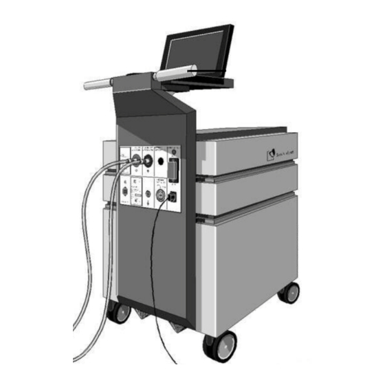
Chapter 5 Description: Ikus Description: Ikus Overview The electro-pneumatic Ikus generates the suction and driving pressures required to drive the blood pump(s). The driving unit contains the pneumatic and electronic components as well as a laptop computer which serves as an interface to the operator. 1 laptop computer with monitor program 2 lifting bar 3 mains cable... -
Page 68: Displays And Operating Elements
LOG files on the Ikus. Never connect other USB devices (e.g. wireless technology) to the USB port of the laptop than the delivered USB stick. If the USB stick is no longer available, contact Berlin Heart, Inc. immediately and request a replacement stick. - Page 69 Chapter 5 Description: Ikus 1 Driving tube connectors, left blood pump, red The plug for the driving tube with the red marking is to be plugged to this connector. 2 Driving tube connectors, right blood pump, blue The plug for the driving tube with the blue marking is to be plugged to this connector.
- Page 70 Chapter 5 Description: Ikus 8 Connector Potential equalization Should several electric devices be positioned in the vicinity of the patient, they are to be connected to a central grounding point. To this end, the connector Potential equalization is to be used on the Ikus. 9 Connector External alarm (Nurse call) This connector serves as the link to the clinic's internal alarm system.
-
Page 71: Display And Operating Panel
Chapter 5 Description: Ikus 5.2.2 Display and operating panel Fig. 5-3 Display and operating panel 1 Battery operation The yellow LED lights up when the Ikus is running in battery operation 2 Alarm The red LED lights up or flashes (design dependent) whenever there is an alarm message which has not been acknowledged by the monitor program 3 Mute alarm (Audio paused) Button to temporarily mute an alarm message. -
Page 72: Operating Modes
Chapter 5 Description: Ikus Failure to do like mentioned above will severely reduce the capacity of the batteries and will greatly shorten the maximum off-mains (battery) operating time! This particularly applies to situations where the Ikus is operated at temperatures exceeding 30 °C. Always monitor the charging level display (see Fig. -
Page 73: Laptop Computer With Monitor Program
Chapter 5 Description: Ikus 5.4 Laptop computer with monitor program NOTICE If the laptop is switched off while the Ikus is in operation, the driving unit will continue to operate using the current parameter settings. The laptop computer is integrated into the Ikus casing. The laptop, with its permanently installed monitor program, is used to start, set up and monitor the system. -
Page 74: Redundant Design Of Pneumatic Systems In Biventricular Operation
Chapter 5 Description: Ikus 5.5.2 Redundant design of pneumatic systems in biventricular operation Each blood pump is powered by 1 pneumatic systems. The 3 system is redundant and serves as a backup. If one of the active systems fails, the 3 (backup) system drives the corresponding pump. -
Page 75: Battery Operation
Chapter 5 Description: Ikus board runs autonomously and can be influenced neither by the 2 control computers nor by the laptop. In emergency pulse mode, the system will operate with the following settings: Synchronous mode (biventricular) Systol. Diastol. Rate Relat. systole pressure pressure duration [%]... - Page 76 Chapter 5 Description: Ikus This page was left blank intentionally 1000721x09 Revision 8...
-
Page 77: Instructions For Use: Ikus
4 hours. If there is a message that indicates action must be taken, take the appropriate action and, if necessary, contact the Berlin Heart, Inc. emergency hotline. When switching on the Ikus, always switch the Ikus on first and then the laptop and not vice versa. -
Page 78: Start Menu
Chapter 6 Instructions for use: Ikus 1 <Caps Lock> 2 Press <Shift> Fig. 6-2 De-activate the Caps Lock 1 Press <NumLk> Fig. 6-3 De-activate the Numeric Lock Start menu After the laptop is started, it will display the menu Select language. Fig. -
Page 79: Selecting An Option In The Start Menu
Chapter 6 Instructions for use: Ikus 2. Entry codes With this option password-protected user profiles (user no.: 1 digit; password: combination of max. 32 digits) for the monitor program can be edited. 3. End This option will shut down the operating system before switching off the laptop. - Page 80 Chapter 6 Instructions for use: Ikus Fig. 6-8 Entry codes INSTRUCTION 1. If the monitor program is running: press <F10> to exit the monitor program. Confirm by pressing <X> or <1>. 2. From the start menu, select 2. Entry-codes (<2>). 3. Enter the default user profile code and confirm the input by pressing <Enter>.
-
Page 81: Saving Data On Usb Stick
Chapter 6 Instructions for use: Ikus 6.1.3 Saving data on USB stick NOTICE Consult the service department before proceeding with this option (refer to section 15.7: Reading out the LOG files, page 207). 6.1.4 Changing date or time Fig. 6-9 Change date or time INSTRUCTION 1. If the monitor program is running: press <F10>... -
Page 82: Shutting Down The Monitor Program
Chapter 6 Instructions for use: Ikus 6.2.2 Shutting down the monitor program WARNING Do not shut down the monitor program unless this is absolutely necessary (e. g. if new user profiles have to be set up). Restart the monitor program as soon as possible. INSTRUCTION 1. Press <F10>... -
Page 83: Standard View - Monitor Program
Chapter 6 Instructions for use: Ikus INSTRUCTION 1. The monitor program is running. It now displays the field User ID. Enter user ID. The monitor program now displays the field Password. 2. Enter the password and confirm the password with <Enter>. The monitor pro gram will now display the field off. -
Page 84: Selecting Monitor Program Options
The messages can be recalled by Berlin Heart's service department. Monitor program functions Monitor and control system: • If required: parameter adjustment... - Page 85 In individual cases, consideration is to be given as to whether a combination that is not recommended is to be selected. The final decision on the combination of blood pumps and cannulae is to be reached by the implanting surgeon, in consultation with Berlin Heart, Inc., Clinical Affairs. 1000721x09 Revision 8...
-
Page 86: Adjusting The Parameter Values
Chapter 6 Instructions for use: Ikus 6.2.7 Adjusting the parameter values NOTICE If the adjusted parameter was not confirmed with <Enter>, the parameter table will display the changed parameter until the automatic log off, but the Ikus will continue operating with the former value. The changed parameter display can be Ed with <Esc>. -
Page 87: Browsing In The Message Window
Chapter 6 Instructions for use: Ikus 6.2.8 Browsing in the message window INSTRUCTION 1. Press the <7> key to move the cursor in the message window. 2. Scroll through the messages: either 1 message at a time with <↓>/ <↑>; or 4 messages at a time with <Bild-↓>/ <Bild-↑>. -
Page 88: Pause Left/ Pause Right: Stopping An Individual Blood Pump
Chapter 6 Instructions for use: Ikus Fig. 6-19 Pump size and single-step mode 3. The cursor is located on the field. In order to restart the driving unit with the current settings, press the <Enter> key. IMPORTANT: If the user leaves field before pressing <Enter>, at least once Step left Step... -
Page 89: Switching Between Mains And Battery Operation
Chapter 6 Instructions for use: Ikus INSTRUCTION 1. Check the following: Are the batteries fully charged? (all yellow charge indica tor LEDs should be lit). If not: Continue as instructed here up to and including step 4. Then switch off the laptop and leave the Ikus switched on until all yel low LEDs light up. - Page 90 Chapter 6 Instructions for use: Ikus When the battery charge is low, the acoustic signal sounds every minute. The Ikus must be connected to the mains operation immediately. ADVICE Always take along the mains cable when operating the Ikus in battery operation.
- Page 91 Chapter 6 Instructions for use: Ikus Behavior of the Ikus with various battery charges What? When? Meaning The charge indicator always charge status shows the battery This does not apply charge status while the batteries are being charged (all yellow LEDs light up only after the batteries have been completely recharged)
-
Page 92: Changing Over From Univentricular To Biventricular Operation
Chapter 6 Instructions for use: Ikus What? When? Meaning Pump stands still - no Batteries are complete Immediately connect the further pump function; emptied or there is a Ikus to the mains. Until acoustic alarm is still serious fault in the that supply the patient audible batteries... -
Page 93: Routine Start-Test When Not In Operation
3. IMPORTANT: Wait 10 minutes. 4. Restart the start-up procedure (see above). If the system again detects an error in the start-up test or not all of the battery LEDs are illuminated after 24 hours, notify Berlin Heart: HOTLINE Notify Berlin Heart! 866.249.0128... -
Page 94: Moving The Ikus
Chapter 6 Instructions for use: Ikus Moving the Ikus 1 handle: push the Ikus 2 lifting bar: the Ikus can be lifted here Fig. 6-21 Handle and lifting bar Transport within the clinic WARNING To move the Ikus unit: push only, using the handle provided for this purpose. -
Page 95: Unloading The Ikus From The Shipping Crate
Chapter 6 Instructions for use: Ikus To transport the Ikus, only the supplied original transport crate must be used. Make sure that the Ikus is standing firmly and securely in the crate and that the crate is closed and sealed properly. The crate must always be transported as marked. -
Page 96: Loading The Ikus Into The Shipping Crate
10. Stand on the ramp and carefully pull out the Ikus by the handle bar. For assistance please: HOTLINE Notify Berlin Heart! 866.249.0128 6.7.2 Loading the Ikus into the shipping crate During transport, the key remains in the main switch (key switch) in the [0] position. - Page 97 Chapter 6 Instructions for use: Ikus Make sure the laptop is closed and in parking position. Fig. 6-23 Prepare the laptop 4. Line up the Ikus with the ramp. Push it upward on the handle bars; all the way into the crate. Fig.
- Page 98 Chapter 6 Instructions for use: Ikus 6. Place the accessory box in front of the Ikus top of the bottom. Fig. 6-25 Place the accessory box 7. Reattach the securing plate. Fig. 6-26 Reattach the securing plate 1000721x09 Revision 8...
- Page 99 Chapter 6 Instructions for use: Ikus Lift up the ramp. Fig. 6-27 Lift up the ramp 9. Fix the ramp with the safety retainer. Fig. 6-28 Fix the ramp 10. Close the front door and apply the latches. Fig. 6-29 Close the door 1000721x09 Revision 8...
-
Page 100: Cleaning And Disinfection Of The Ikus
Chapter 6 Instructions for use: Ikus 11. Lock the crate with a cable binder. Fig. 6-30 Lock the crate 12. The crate is now ready for storage/ shipping. Fig. 6-31 Crate ready for storage/ shipping Cleaning and disinfection of the Ikus WARNING Prevent liquids from spilling into the Ikus. - Page 101 Chapter 6 Instructions for use: Ikus INSTRUCTION Clean Ikus by wiping disinfection with an alcohol containing solution ® (e.g. Bacillol plus). IMPORTANT: Do not expose display and keyboard to direct spray jet, but use a cloth that is moistent with disinfecting agent. 1000721x09 Revision 8...
- Page 102 Chapter 6 Instructions for use: Ikus This page was left blank intentionally 1000721x09 Revision 8...
-
Page 103: Commissioning The Ikus And Setting Parameters
Chapter 7 Commissioning the Ikus and setting parameters Commissioning the Ikus and setting parameters WARNING Before starting the Ikus, make sure that a replacement Ikus is available in the hospital. If a replacement Ikus is not available, there is a risk that the patient cannot be cared for in the event of device malfunction. -
Page 104: Connecting The Tank Unit
Chapter 7 Commissioning the Ikus and setting parameters The Ikus power switch (toggle switch) should always be in the [I] position, even if the Ikus is set to [0] position at the main switch (key switch)! Otherwise the driving unit may stop completely because the batteries have become fully depleted. -
Page 105: Switching On The Ikus
Chapter 7 Commissioning the Ikus and setting parameters INSTRUCTION Remove the seal plugs from the driving tube connection socket. 2. Connect the plug of the 2 tank units to the driving tube connection sockets. 7.1.2 Switching on the Ikus WARNING The Ikus must always be connected to the power supply when it is switched on. - Page 106 3. Wait for at least 10 minutes. 4. Commence the start procedure again (see section 7.1.3: Starting the monitor program, page 95). If Ikus detects a fault again: Do not use this Ikus. HOTLINE Notify Berlin Heart! 866.249.0128 1000721x09 Revision 8...
-
Page 107: Intraoperative Drive Management
The Ikus will repeat the connector seal test up to 3 times. If the test is still not successful, the system will switch itself off. Please contact the emergency hotline. HOTLINE Notify Berlin Heart! 866.249.0128 INSTRUCTION 1. The message Please close right outlet is shown. -
Page 108: Select The Pump Size
In individual cases, consideration is to be given as to whether a combination that is not recommended is to be selected. The final decision on the combination of blood pumps and cannulae is to be reached by the implanting surgeon, in consultation with Berlin Heart, Inc., Clinical Affairs. Fig. 7-4... -
Page 109: Display Pump And Cannula Sizes
Chapter 7 Commissioning the Ikus and setting parameters Fig. 7-5 Cannula in for the left pump INSTRUCTION 1. From the pop-up menu Cannula in for the left pump, select the inflow cannula size for the left pump with <↓>,<↑>. 2. Move cursor with <←>/<→> to the pop-up menu Cannula out for the left pump. -
Page 110: Setting The Start-Up Parameters
Chapter 7 Commissioning the Ikus and setting parameters Fig. 7-6 Display pump and cannula sizes 7.2.6 Setting the start-up parameters WARNING To connect the blood pump(s), always set the start-up parameters! Fig. 7-7 Pump size and single-step mode 1000721x09 Revision 8... -
Page 111: Connecting The Blood Pump(S) To The Ikus
Chapter 7 Commissioning the Ikus and setting parameters INSTRUCTION 1. Place the cursor with <↑> in the parameter table and navigate with <←>/ <→> to the desired field in the parameter table. Adjust with <↓>, <↑> /<Bild-↓>, <Bild-↑> then confirm with <Enter>. 2. Set the start-up parameters: Systole [mmHg] Diastole... -
Page 112: Airing The Blood Pumps In Single-Step Mode
Chapter 7 Commissioning the Ikus and setting parameters 7.2.8 De-airing the blood pumps in single-step mode NOTICE Each de-airing step (Step left/ Step right) carries out half a pump cycle (systole or diastole), the 1 step being a diastole. Normally, several de- airing steps are required for each pump. -
Page 113: Checking The Parameters When The Pump Is Started And Adjusting Them
Chapter 7 Commissioning the Ikus and setting parameters 7.2.10 Checking the parameters when the pump is started and adjusting them WARNING In order to avoid air being sucked into the blood pump through the cannula anastomosis, adjust the parameters gradually. If air does enter the system, disconnect the driving tubes from the Ikus and de-air the system using the de-airing needle. - Page 114 Chapter 7 Commissioning the Ikus and setting parameters Keep the following points in mind with regard to filling of the right pump: The aim is to reduce the right ventricle’s load to a large extent but not completely. Signs that the RV load has been reduced completely are: • filling of the pump depends largely on the respiratory cycle • ventricle is empty/limp • membrane stops abruptly during filling...
-
Page 115: Switching From Cpb Support To Vad Support
Chapter 7 Commissioning the Ikus and setting parameters INSTRUCTION 1. Use the <←>/<→> keys to move the cursor to the field showing the current operating mode. A pop-up menu showing the available operating modes is opened (see Tab. 7-3, page 101). 2. Select the desired operating mode with <↓>,<↑>... -
Page 116: Possible Complications
Chapter 7 Commissioning the Ikus and setting parameters INSTRUCTION 1. When the blood pump(s) starts to fill, reduce the CPB flow and gradually increase the EXCOR rate from an initial 30 bpm until CPB has been termi nated and the required flow is achieved. IMPORTANT: In doing so, make sure that the pump fills adequately, and if necessary regulate the driving pressure. -
Page 117: Postoperative Drive Management
Chapter 7 Commissioning the Ikus and setting parameters Incomplete ejection right/left INSTRUCTION 1. Observe the arterial blood pressure, and at the same time observe the ejection movement of the pump membrane. 2. If complete emptying of the pump is no longer achieved, adjust the driving pressure accordingly. - Page 118 Chapter 7 Commissioning the Ikus and setting parameters This page was left blank intentionally 1000721x09 Revision 8...
-
Page 119: Implantation: Preparations In The Operating Room
Chapter 8 Implantation: Preparations in the operating room Implantation: Preparations in the operating room 8.1 Preparing the components and materials required NOTICE Selection of blood pump(s): see section 16.1: Overview: Product range and possible combinations, page 211. ADVICE It is advantageous to provide a sterile table on which to place the prepared sterile components. - Page 120 Chapter 8 Implantation: Preparations in the operating room Fig. 8-1 Cable tie gun INSTRUCTION 1. Check if the following values are set: • coarse adjustment on STD (2) • fine adjustment on 5 (1) Fig. 8-2 Checking the adjustment 2. In the case of deviations loosen the screw (4) and disassemble the locking cap (3).
-
Page 121: Unpacking The Sterile Components
Chapter 8 Implantation: Preparations in the operating room 3. Adjust the above-mentioned val ues with the adjusting wheels (6 and 5). Begin with adjusting wheel Fig. 8-4 Adjusting the settings 4. Assemble the locking cap (3) and secure it with the screw (4). Fig. -
Page 122: Moving The Membrane To The End-Of-Diastole Position
Chapter 8 Implantation: Preparations in the operating room Moving the membrane to the end-of-diastole position 1 de-airing nipple (blood chamber) 2 driving tube connector (air chamber) Fig. 8-6 De-airing nipple and driving tube connector INSTRUCTION 1. Pick up adapter tube, disposable syringe (membrane set) and the pump. 2. Connect the adapter tube to the disposable syringe. -
Page 123: Inserting The De-Airing Needle
Chapter 8 Implantation: Preparations in the operating room 1 blood chamber 2 de-airing nipple 3 trocar (de-airing needle with obturator in place) 4 membrane in end-of-diastole position 5 air chamber 6 de-airing needle 7 obturator trocar Fig. 8-7 Pump with trocar in place (de-airing needle with inserted obturator) 8.5.1 Inserting the de-airing needle WARNING... - Page 124 Chapter 8 Implantation: Preparations in the operating room INSTRUCTION 1. Push the free end of the de-airing tube onto the trocar as far as it will go. Secure the de-airing tube to the trocar with a suture tie. 3. Fill the syringe with sterile injectable saline. 4. Connect the syringe to the stopcock end of the de-airing tube.
-
Page 125: Implantation - Surgical Procedure
Chapter 9 Implantation - surgical procedure Implantation - surgical procedure This chapter describes the product-specific measures to be observed when implanting an EXCOR blood pump. The setting of the Ikus parameters during and after implantation is described in chapter 7: Commissioning the Ikus and setting parameters, page 93. -
Page 126: Cannula Exit Sites
Chapter 9 Implantation - surgical procedure ADVICE For BVAD, carry out anastomosis of the cannulae in the following order: apical cannulation: 1. LV apex 2. right atrium 3. pulmonary artery 4. aorta atrial cannulation: 1. left atrium 2. right atrium 3. -
Page 127: Use Of The Cannula Tunneling Tip
Chapter 9 Implantation - surgical procedure Use of the cannula tunneling tip The cannula tunneling tip is a sterile disposable product and is supplied with each cannula. Sizes available: see section Fig. 9-3: Available sizes of cannula tunneling tips, page 117. Staged cannulae are supplied with 2 different tunneling tips. INSTRUCTION 1. Push the cannula tunneling tip firmly into the distal end of the cannula. -
Page 128: Description: Cannula Extension And Connecting Sets
9.3.1 Description: Cannula extension and connecting sets Berlin Heart supplies connecting sets to bridge different connector diameters in the blood pump and cannula (6/9, 9/12). This allows for greater flexibility when combining blood pumps and cannulae. The connecting set may be used during implantation or during the further course of therapy. -
Page 129: Instructions For Use: Cannula Extension Set And Connecting Set
Chapter 9 Implantation - surgical procedure These sets could be neccessary in the following contexts: • during implantation • when replacing a blood pump • when cutting off a piece of cannula (due to visible deposits or damaged cannula) The cannula extension set / connecting sets thus guarantee that the blood pump and cannulae can still be safely connected with one another and that the cannulae and titanium connectors on the blood pump can still be visually inspected. - Page 130 Chapter 9 Implantation - surgical procedure When using a cannula extension set / a connecting set it may be necessary to shorten the respective connecting tube, but the minimum length must be maintained. See Tab. 9-1, page 120. Article Diameter / Minimum length Diameter reduction Cannula extension set...
-
Page 131: Access
Chapter 9 Implantation - surgical procedure During implantation/ When replacing a blood pump INSTRUCTION 1. Connect the cannula extensions (the connectors resp.) with the blood pump. To do so, push the section of the cannula extension (the connector resp.) onto the titanium connector of the blood pump. -
Page 132: Anastomosis Of Inflow Cannula With Lv Apex
Chapter 9 Implantation - surgical procedure 9.5.1 Anastomosis of inflow cannula with LV apex WARNING During anastomosis of the LV apex cannula, make sure that the cannula head is facing in the right direction: the long side of the head should be parallel to the lateral wall. -
Page 133: Creating A Transcutaneous Tunnel For The Lv Apex Cannula
Chapter 9 Implantation - surgical procedure 1 Long side of LV apex cannula head Fig. 9-8 Head of LV apex cannula 9.5.2 Creating a transcutaneous tunnel for the LV apex cannula WARNING Always use the cannula tunneling tip provided (see section 9.2: Use of the cannula tunneling tip, page 117) to advance the cannula through the prepared transcutaneous tunnel. -
Page 134: Atrial Cannula(E)
Chapter 9 Implantation - surgical procedure 3. Tunnel the LV apex cannula through the transcutaneous passage by using a pair of forceps to firmly grip the flat end piece of the tunneling tip and pull it through the cannula tunnel and the skin incision. IMPORTANT: Do not rotate the cannula while pulling it through the tunnel. -
Page 135: Anastomosis Of Atrial Cannulae
Chapter 9 Implantation - surgical procedure Plan the cannula exit sites appropriately. Leave an adequate bridge of skin and subcutaneous tissue between the cannula exit incisions to prevent breakdown and necrosis of the skin and tissue. If possible the cannula exit in sic ions should be on different planes. INSTRUCTION 1. Prepare the transcutaneous tunnel. -
Page 136: Arterial Cannula(E)
Chapter 9 Implantation - surgical procedure Left atrium The procedure for anastomosis of the left atrium corresponds to the procedure applied to the right atrium. ADVICE Place anastomosis at the junction of the right upper pulmonary vein and the left atrium. The atrial wall is the recommended implantation location. -
Page 137: Anastomosis Of The Arterial Cannula
Chapter 9 Implantation - surgical procedure 9.7.2 Anastomosis of the arterial cannula Aorta INSTRUCTION 1. Tangentially clamp the ascending aorta and make a longitudinal opening of a length which is suit able for the cannula diameter. If necessary, offset the incision later ally to the right by up to 45°. -
Page 138: Shortening The Cannulae If Necessary
Chapter 9 Implantation - surgical procedure Shortening the cannulae if necessary WARNING If an EXCOR cannula extension set / connecting set is required for implantation and the length of the tube part needs to be reduced, the tube part should be cut but only to achieve the following minimum lengths: Article Diameter /... - Page 139 Chapter 9 Implantation - surgical procedure Type of support Anastomosis of inflow Points upwards... cannula to Biventricular LVAD apex blood chamber LVAD atrium air chamber RVAD atrium air chamber Tab. 9-3 Anastomosis and direction of the blood chambers NOTICE Finally, the driving tube is connected to the Ikus. The Ikus is started and the parameters are gradually adjusted (see section 7.2.10: Checking the parameters when the pump is started and adjusting them, page 103).
-
Page 140: Removing The De-Airing Needle
Chapter 9 Implantation - surgical procedure 9.10 Removing the de-airing needle WARNING When removing the de-airing needle, never pull on the de-airing tube, but on the de-airing needle itself. Before removing the de-airing needle, be sure that the de-airing tube is secured to the de-airing needle. - Page 141 Chapter 9 Implantation - surgical procedure 3. The 1 cable tie must be positioned exactly on the groove profile of the connector (1). IMPORTANT: the heads of the cable ties have to be directed away from the patient‘s body. 4. Fasten the cable ties by the cable tie gun.
- Page 142 Chapter 9 Implantation - surgical procedure This page was left blank intentionally 1000721x09 Revision 8...
-
Page 143: Implantation - Anesthesia
Chapter 10 Implantation - anesthesia Implantation - anesthesia The following risk factors should be closely monitored for anesthetic and hemodynamic management: • right heart function during LVAD implantation • coagulopathy • renal insufficiency • abnormal reactions to inotrope administration • pulmonary hypertension CAUTION There should be an adequate supply of pre-matched stored blood, fresh frozen plasma and platelet concentrates available for immediate... - Page 144 Chapter 10 Implantation - anesthesia Any other monitoring processes can be used (e. g. neurological monitoring) at the anesthesiologist’s discretion. 1000721x09 Revision 8...
-
Page 145: Wound Care And Treatment
Chapter 11 Wound care and treatment Wound care and treatment Cannula exit sites should be treated like open wounds. The patient’s wounds should always be attended to by a small group of nurses in the inpatient area. The only way to ensure there is a minimum risk of infection is to provide good wound care. -
Page 146: Removing The Old Dressings
Chapter 11 Wound care and treatment Material required (with biventricular access): • Sterile dressing tray • Disinfectant i.e. 2% chlorhexidine solution • Clean gloves • Mask • Sterile gloves and towel ® • Metalline drain compress • 2X2 gauze, 4X4 gauze • Adhesive dressing (i.e. -
Page 147: Cleaning The Blood Pump
INSTRUCTION 1. Hand hygiene, prepare sterile dressing tray, put on sterile gloves. If assistance is necessary notify Berlin Heart. 2. 4X4 gauze soaked in 2% chlorhexi dine cleanse each cannula exit site in a circular motion outward to a radius of approximately 10 cm. -
Page 148: The New Dressing
Chapter 11 Wound care and treatment 6. Cleanse entire cannula (upper and bottom side). 7. 4X4 gauze soaked in 2% chlorhexi dine solution. 8. Starting at the exit site moving down cannula approximately 10 cm from exit site. 9. Repeat for each cannula exit site. 10. Allow chlorhexidine to dry com... - Page 149 Chapter 11 Wound care and treatment 2. Attach the Metalline drain com presses above the cannulae using sterile bandages. First secure the outer compresses, then the inner compresses. Fig. 11-9 Secure with a sterile bandage 3. Pass a gauze compress folded lengthwise beneath the 2 left can ...
- Page 150 Chapter 11 Wound care and treatment 6. Repeat this procedure for the 2 right cannulae. In this way, the 4 cannulae are padded so that they do not press on the skin or wound. Fig. 11-13 Cannulae are padded 7. Cover the entire wound broadly with gauze compresses.
-
Page 151: Regular Checks Of Blood Pump(S) And Cannulae
Chapter 11 Wound care and treatment 11.5 Regular checks of blood pump(s) and cannulae Frequency of inspection: every 4 hours WARNING Everyone involved in caring for an EXCOR patient must be trained to carry out a visual check, to evaluate the filling behavior of the blood pump(s) and to detect deposits. -
Page 152: Visual Inspection: Deposits
Chapter 11 Wound care and treatment Adjusting the parameter values Only adjust the parameters if the measures listed above have no effect or in case of: • Mobilization of patient: adjust the systolic pressure, both left and right. When pressures have increased, do not reduce these again, even when the patient is lying down. -
Page 153: Checks Using The Monitor Program
Chapter 11 Wound care and treatment Checking the pump areas which come in contact with blood 1 transition inflow cannula – inflow connector 2 inflow stub in front of inflow valve 3 inflow valve 4 inflow stub behind inflow valve 5 area between inflow and outflow stubs 6 remaining area of blood chamber 7 transition blood chamber - membrane (directly... -
Page 154: Replacing The Blood Pump Due To Growth Of The Patient
This chart is for guideline purposes only and is not binding for each individual case. This decision must be taken by the surgeon in consultation with Berlin Heart GmbH. HOTLINE Notify Berlin Heart! 866.249.0128 The blood pump(s) must be replaced as described in section 15.1: Replacing the... -
Page 155: Anticoagulation Therapy
® The TEG may be useful in managing unfractionated heparin and antiplatelet therapy. Please contact Berlin Heart, Clinical Affairs for further information. 12.1.2 Pre implantation The following laboratory tests should be considered prior to implantation. • Platelet Function Studies, INR, PTT, fibrinogen, antithrombin III, and platelet count to establish a baseline. -
Page 156: Unfractionated Heparin Therapy (I.v.) Patient < 12 Months
Chapter 12 Anticoagulation therapy Approximately 24 - 48 hours after implantation, commence unfractionated heparin therapy (i.v.) if the following criteria are met: • Platelet count >20,000/µl • Normal Platelet Function Studies • Minimal bleeding in infants and young children. 12.3.3 Unfractionated heparin therapy (i.v.) Patient < 12 months • Initial dose 15 IU/kg/hour. -
Page 157: Thrombelastography (Teg®)
® analysis may be useful in managing the anticoagulation and anti-platelet therapy. Please contact Berlin Heart Inc., Clinical Affairs for further information. 12.4 Low Molecular Weight Heparin At 48 hours following surgery if all bleeding has stopped, the creatinine is within normal limits, and the patient is hemodynamically stable, switching from unfractionated heparin to low molecular weight heparin (LMWH) is recommended. -
Page 158: Monitoring Of Blood Count And Anticoagulation Status
Chapter 12 Anticoagulation therapy 4 weeks, twice a week for the next 4 weeks (if INR is stable), and once a week there after (see Tab. 12-3, page 151 and Tab. 12-4, page 151. Until the target INR is achieved, simultaneous administration of warfarin and heparin is necessary (approximately 4 days). -
Page 159: Adjunctive Medication
Chapter 12 Anticoagulation therapy Acetylsalicylic Acid At 4 days post implantation, following the removal of all drainage tubes, start acetylsalicylic acid (ASA) 1mg/kg/day p.o., divided into 2 doses (0.5 mg/kg Q 12), if the following are present: • Platelet studies show platelet inhibition in the presence of AA < 70 % The ASA dose should split and be administered two times daily (0.5 mg/kg Q 12) due to the short half life and the high turnover of the platelets (approximately 10 % new platelets per day). - Page 160 Chapter 12 Anticoagulation therapy Stage Description Anti factor Xa Infusion Hold Rate Repeat [u/ml]/PTT heparin Change Initial Dose (first 6 hours) Infant 15 IU/kg/h < 12 mo Child 10 IU/kg/h ≥12mo Therapeutic Dose Infant 28 IU/kg/h after 6h < 12 mo Child 20 IU/kg/h after 6h...
- Page 161 Chapter 12 Anticoagulation therapy Anti Factor Xa Hold Next Dose Change? Repeat Anti Factor Xa? level U/ml? Dose? 1.6 - 2.0 yes for 3h decrease dose by 40 % Before next dose then 4h after next dose > 2.0 yes, until anti decrease dose by 50% Before next dose is factor Xa admini-stered, if >0.5 U/...
- Page 162 Chapter 12 Anticoagulation therapy This page was left blank intentionally 1000721x09 Revision 8...
-
Page 163: Weaning And Explantation For Btr And Btt
This protocol reflects the most recent understanding of the safest possible weaning strategy based on the collective US and European experience to date. Consultation with Berlin Heart, Inc. prior to weaning and explantation is strongly recommended. -
Page 164: Weaning Protocol
Chapter 13 Weaning and Explantation for BTR and BTT 13.1.4 Weaning Protocol WARNING Rates < 60 bpm are intended to be used only for implantation and explantation. Never use the Ikus with a rate < 60 bpm without constant supervision. If the patient does not meet the eligibility criteria at any time during the weaning process: Resume pumping at rate prior to any weaning (initial rate, IR). - Page 165 Chapter 13 Weaning and Explantation for BTR and BTT Reduced rate (RR Calculation Please enter: = WR 50 bpm + 0.75 x TWI ( ___ bpm) = ____bpm Please enter: = WR 50 bpm + 0.50 x TWI ( ___ bpm) = ____bpm Please enter: = WR 50 bpm + 0.25 x TWI ( ___ bpm) = ____bpm Tab.
- Page 166 Chapter 13 Weaning and Explantation for BTR and BTT 10 ml / 15 ml pump Weaning Sequence After confirmation of eligibility criteria, the following steps should be performed sequentially under echo guidance 1. Administer UFH 75 units/kg x _____ kg = _____ mg IV x 1 [max 5000 units].
- Page 167 Chapter 13 Weaning and Explantation for BTR and BTT 10 ml / 15 ml pump Weaning Sequence After confirmation of eligibility criteria, the following steps should be performed under echo guidance 1. Administer UFH 75 units/kg x _____ kg = _____ mg IV x 1 [max 5000 units].
-
Page 168: 30 Ml Pump
Chapter 13 Weaning and Explantation for BTR and BTT 10 ml / 15 ml pump Weaning Sequence After confirmation of eligibility criteria, the following steps should be performed in the cath lab under echo guidance 1. Obtain standard access for RHC (if possible with out sedation). 2. - Page 169 Chapter 13 Weaning and Explantation for BTR and BTT Parameter Explanation Abbr. Value total weaning Difference between Please enter: interval initial rate and IR ___ bpm - WR 40 bpm = explantation rate: TWI ___ bpm TWI = IR - WR reduced rate rate resumed at the Please refer Tab.
- Page 170 Chapter 13 Weaning and Explantation for BTR and BTT 25 / 30 ml pump Weaning Sequence After confirmation of eligibility criteria, the following steps should be performed sequentially under echo guidance: Administer UFH 75 units/kg x _____ kg = _____ mg IV x 1 [max 5000 units].
- Page 171 Chapter 13 Weaning and Explantation for BTR and BTT 25 / 30 ml pump Weaning Sequence After confirmation of eligibility criteria, the following steps should be performed under echo guidance: Administer UFH 75 units/kg x _____ kg = _____ mg IV x 1 [max 5000 units].
-
Page 172: 60 Ml Pump
Chapter 13 Weaning and Explantation for BTR and BTT 25 / 30 ml pump Weaning Sequence After confirmation of eligibility criteria, the following steps should be performed in the cath lab under echo guidance: Obtain standard access for RHC (if possible with out sedation). Administer UFH 75 units/kg x _____ kg = _____ mg IV x 1 [max 5000 units]. - Page 173 Chapter 13 Weaning and Explantation for BTR and BTT Parameter Explanation Abbr. Value total weaning Difference between Please enter: interval initial rate and IR ___ bpm - WR 30 bpm = explantation rate: TWI ___ bpm TWI = IR - WR reduced rate rate resumed at the Please refer to Tab.
- Page 174 Chapter 13 Weaning and Explantation for BTR and BTT 50 / 60 ml pump Weaning Sequence After confirmation of eligibility criteria, the following steps should be performed sequentially under echo guidance: Administer UFH 75 units/kg x _____ kg = _____ mg IV x 1 [max 5000 units].
- Page 175 Chapter 13 Weaning and Explantation for BTR and BTT 50 / 60 ml pump Weaning Sequence After confirmation of eligibility criteria, the following steps should be performed under echo guidance: Administer UFH 75 units/kg x _____ kg = _____ mg IV x 1 [max 5000 units].
-
Page 176: Explantation Criteria
Chapter 13 Weaning and Explantation for BTR and BTT 50 / 60 ml pump Weaning Sequence After confirmation of eligibility criteria, the following steps should be performed in the cath lab under echo guidance Obtain standard access for RHC (if possible with out sedation). Administer UFH 75 units/kg x _____ kg = _____ mg IV x 1 [max 5000 units]. -
Page 177: Explantation For Btr
Chapter 13 Weaning and Explantation for BTR and BTT In the operating room, explantation should be considered if the following criteria are met with the pump stopped for 20 minutes (after anticoagulation has been established in the target range for cardiopulmonary bypass): •... -
Page 178: Explantation For Btt
Chapter 13 Weaning and Explantation for BTR and BTT Do not switch the Ikus off unless the batteries are fully charged. Leave the Ikus switched on until all yellow LEDs light up, then switch off the Ikus with main switch (key switch). Keep all driving tube connectors covered at all times when not in use. - Page 179 Chapter 13 Weaning and Explantation for BTR and BTT CAUTION Always follow the above sequence of operations. Always use the key switch to switch off the Ikus. Do not switch the Ikus off unless the batteries are fully charged. To do this leave the Ikus switched on until all yellow LEDs light up, then switch the Ikus off using the key switch.
- Page 180 Chapter 13 Weaning and Explantation for BTR and BTT Removing the VAD cannulae INSTRUCTION Clamp off the cannulae. Disconnect the pump from the cannulae. Remove the cannulae. Sew over the anastomosis areas of the atrium. The remaining procedure is the same as for any primary orthotopic heart transplantation.
-
Page 181: Error Messages And Corrective Measures
Ikus treats all error messages with the same priority. HOTLINE Notify Berlin Heart! 866.249.0128 NOTICE Some errors immediately re-trigger an alarm as long as they are still active even after being acknowledged on the laptop. Also in this case first mute the alarm on the handle in order to prevent permanent retriggering of the acoustic alarm. - Page 182 Chapter 14 Error Messages and corrective measures Acknowledging an error message WARNING Messages are only displayed when the monitor program is running. When the monitor program is shut down, the only indications that there is an error message are an acoustic signal and the fact that the indicator lamp on the Ikus handle lights up.
-
Page 183: Pressure Error / Time Error In System 1 (Or In System 2 Or 3)
Contact customer service. is shown (see section 14.5: Backup operation left/right, page 176), together with a request to inform the service department. HOTLINE Notify Berlin Heart! 866.249.0128 If the Ikus has detected an external fault … it displays the message Please connect driving tube! (see section 14.3: Please connect driving tube, page 174). -
Page 184: Please Connect Driving Tube
Chapter 14 Error Messages and corrective measures 14.3 Please connect driving tube Please connect driving tube! INSTRUCTION 1. Inspect the driving tube and the connectors. 2. If a plug is not seated correctly: re-insert it correctly. To do so, grip the release sleeve and pull it out of the connector, then plug it back in. -
Page 185: Please Check Left / Right Pump And Driving Tube
Chapter 14 Error Messages and corrective measures 10. The system starts up again using the defined parameters. 11. Check whether the pump is filling correctly and, if necessary, adjust the Ikus parameters. 12. Secure the pump end of the driving tube with a cable tie strap. Important: Only the cable ties and cable tie guns provided should be used. -
Page 186: Backup Operation Left/Right
8. If the message appears again, check if it is necessary to adjust the cannulae. If the message appears again: HOTLINE Notify Berlin Heart! 866.249.0128 14.5 Backup operation left/right • Backup operation (right). Contact costumer service •... -
Page 187: Emergency Operation System 1 (Or System 2 Or 3). Contact Service Now
Chapter 14 Error Messages and corrective measures HOTLINE Notify Berlin Heart! 866.249.0128 14.6.2 Emergency operation system 1 (or system 2 or 3). Contact Service now! • Emergency operation System 1. Contact service now! • Emergency operation System 2. Contact service now! •... -
Page 188: System 3 (Backup) Is Defective
The Ikus runs in emergency operating mode. Provide the patient immediately with a replacement Ikus. INSTRUCTION Provide the patient immediately with a replacement Ikus. HOTLINE Notify Berlin Heart! 866.249.0128 14.9 Alarm circuit fault: buzzer remains off (or on) • Alarm circuit test failed - buzzer remains off! •... -
Page 189: Backup Computer
Chapter 14 Error Messages and corrective measures HOTLINE Notify Berlin Heart! 866.249.0128 14.11 Backup computer 14.11.1... reports discrepancy in left/right pump output measurements! • Backup computer: discrepancy in left pump output measurement • Backup computer: discrepancy in right pump output measurement The main computer has detected a flow error. -
Page 190: Reports Faulty Test
<Enter>. The system works with the new value.. If the message appears again: HOTLINE Notify Berlin Heart! 866.249.0128 14.11.4... reports faulty test Backup computer reports faulty test The main computer cannot end the test phase to check the system after the error message...(See section 14.1: Pressure error / time error in system 1 (or in system 2... -
Page 191: Parameter Set Update Failure
INSTRUCTION Provide the patient immediately with a replacement Ikus. HOTLINE Notify Berlin Heart! 866.249.0128 14.13 Parameter set update failure The Ikus cannot store the changed parameter values in the internal system memory. The driving unit is operating with the changed values, but if a reset were to be performed, the old values would be valid again. -
Page 192: Fault: <<16-Digit Binary Code>> (<
8 digits! If necessary the service department will request to read out the LOG files and send a copy to Berlin Heart, Inc. (see section 15.7: Reading out the LOG files, page 207). 14.15 Fault: <<16-digit binary code>> (<<type of fault>>) •...>) -
Page 193: Insufficient Battery Charge. Only Limited Battery Operation
(see section 15.5: Driving blood pump(s) with the manual pump, page 204) HOTLINE Notify Berlin Heart! 866.249.0128 If the batteries reach a sufficient state of charge the message Battery charge OK. appears. 14.18 Error messages - Circuit breaker and internal battery fuse •... -
Page 194: Acoustic Alarm Is Not Properly Recognized
(see section 15.5: Driving blood pump(s) with the manual pump, page 204) HOTLINE Notify Berlin Heart! 866.249.0128 14.20 Acoustic alarm is not properly recognized If the message Acoustic alarm: OK appears within 8 seconds after the error message, the Ikus is working perfectly. -
Page 195: Left/Right Flow Sensor Defective. Notify Service
If no replacement Ikus is available and the defective Ikus is halted: Support the patient with the manual pump. (see section 15.5: Driving blood pump(s) with the manual pump, page 204). HOTLINE Notify Berlin Heart! 866.249.0128 14.22 Left/right flow sensor defective. Notify Service! • Left flow sensor fault. Contact customer service. -
Page 196: Problem: <
(see section 15.5: Driving blood pump(s) with the manual pump, page 204) HOTLINE Notify Berlin Heart! 866.249.0128 14.23 Problem: <<Text>> If this message appears during the start-up test:: see section 14.25: Error messages during the start-up test, page 187. -
Page 197: Error Messages During The Start-Up Test
(see section 15.5: Driving blood pump(s) with the manual pump, page 204) HOTLINE Notify Berlin Heart! 866.249.0128 14.25 Error messages during the start-up test In addition to the error messages listed below there are additional messages possible that are described in chapter 12. Always take those measures corresponding to the indicated messages. -
Page 198: Discrepancy In Pressure Measurement: System 1 (Or System 2 Or 3)
INSTRUCTION 1. Do not start up the Ikus. Provide the patient immediately with a replacement Ikus. HOTLINE Notify Berlin Heart! 866.249.0128 14.26 Discrepancy in pressure measurement: system 1 (or system 2 or 3) • Discrepancy in pressure measurement: system 1 (left) •... -
Page 199: Communication With Laptop Failed
The information message Discrepancy in pressure measurement: system 1 (2 or 3) is not accompanied by an acoustic signal. HOTLINE Notify Berlin Heart! 866.249.0128 14.27 Communication with Laptop failed This message informs the user that the communication between the control computers and the monitor program has been temporarily interrupted. - Page 200 Chapter 14 Error Messages and corrective measures This page was left blank intentionally 1000721x09 Revision 8...
-
Page 201: Troubleshooting And Correcting Faults
Chapter 15 Troubleshooting and correcting faults Troubleshooting and correcting faults HOTLINE Notify Berlin Heart! 866.249.0128 Problem Cause of problem / action to be taken Deposits in the Initial deposits: check anticoagulation status and adjust pump therapy if necessary. If floating deposits are detected (may cause thromboembolic complication): replace the pump, see section 15.1: Replacing the blood pump(s), page 195. - Page 202 Check if the condensate will leave in the next days. Contact Berlin Heart. Flapping or Possible cause: fluttering of Partial rupture of one or two layers of the triple-layer membrane during membrane.
- Page 203 Ikus has the above error(s), then follow the directions associated with the error message on the Ikus; see chapter 14: Error Messages and corrective measures, page 171: Visible Ikus faults Notify Berlin Heart. Tab. 15-1 Possible problems 1000721x09 Revision 8...
- Page 204 Error: no reaction from What to do? Master Assess the condition of the patient and the hemodynamic values. Notify Berlin Heart immediately. Pump stands still - Possible causes no further pump • complete failure of the Ikus function; acoustic •...
-
Page 205: Replacing The Blood Pump(S)
Chapter 15 Troubleshooting and correcting faults 15.1 Replacing the blood pump(s) WARNING When replacing a blood pump, follow the instruction given here. Otherwise the duration of the pump stop will be prolonged and the patient might suffer from inadequate support. The blood pump may only be replaced under sterile conditions! All effort should be made to minimize the manipulation and distortion of the blood pumps and cannula during the removal of the cable tie(s) to... -
Page 206: Replacing The Right Blood Pump (Rvad/ Bvad)
Chapter 15 Troubleshooting and correcting faults INSTRUCTION 1. Bring membrane to the end-of-diastole position, position de-airing needle, rinse and fill pump with sterile injectable saline (see section 8.4: Moving the membrane to the end-of-diastole position, page 112 and section 8.5: De-airing the blood pump, page 112). -
Page 207: Replacing The Left Blood Pump (Lvad/ Bvad)
Chapter 15 Troubleshooting and correcting faults Connect new right blood pump to the Ikus INSTRUCTION 1. Fill the free ends of the cannulae with sterile saline solution. Make sure that all air has been removed. Connect the prepared replacement pump to the cannu lae. -
Page 208: Restarting Ikus
Chapter 15 Troubleshooting and correcting faults 3. If necessary log into the monitor program by entering user ID and password, confirming the password with <Enter>. 4. In the monitor program, select the option Pause left respectively Drive pause and press <Enter> to confirm. Respond to the prompt in the dialog window by pressing the <X>... - Page 209 Chapter 15 Troubleshooting and correcting faults The Ikus power switch (toggle switch) should always be in the [I] position, even if the main switch (key switch) is in the [0] position!. Otherwise there is a risk that the drive may fail in future due to the Ikus batteries being totally discharged.
-
Page 210: Emergency Pulse Mode
In emergency pulse mode the system operates with the following settings: Synchronous mode (biventricular) Systol. Diastol. Rate relat. systole pressure pressure duration [%] [bpm] [mmHg] [mmHg] left right Tab. 15-2 Settings in emergency pulse mode Always immediately … HOTLINE Notify Berlin Heart! 866.249.0128 1000721x09 Revision 8... -
Page 211: Emergency Pulse Mode - Switching The Ikus Off
4. Switch off the Ikus. To do so, turn the key switch to [0] position. 15.3.2 Ikus start-test following emergency pulse mode WARNING Do not reconnect the original Ikus to the patient until the Berlin Heart, Inc. service department has evaluated the LOG files or has serviced the driving unit. -
Page 212: Connecting The Patient To A Replacement Ikus
Chapter 15 Troubleshooting and correcting faults 7. Respond to the prompt in the dialog window by pressing the <X> key or the <1> key. The system stops operation immediately and writes an operating log. 8. Wait until the log has been completed (message: Switch off drive with main switch!). - Page 213 Chapter 15 Troubleshooting and correcting faults Systole Diastole Rate Rel. diast. Operation mode [mmHg] [mmHg] [bpm] duration [%] left/ right left/ right left/ right 210/ 130 -40/ -20 40/40 biventricular, synchronous and separate Tab. 15-3 Default standard parameters INSTRUCTION 1. Select the desired language by pressing the corresponding number key. It is not necessary to press <Enter>...
-
Page 214: Driving Blood Pump(S) With The Manual Pump
Chapter 15 Troubleshooting and correcting faults 3. As soon as the original Ikus has stopped, remove the driving tube(s) from it. To do so, take hold of the release sleeve and pull this out of the connector(s). 4. Connect the driving tube(s) to the replacement Ikus. IMPORTANT: Observe the colored markings. - Page 215 Chapter 15 Troubleshooting and correcting faults Call one or more persons to assist. Otherwise in an emergency situation the adequate support of the patient is not guaranteed. The driving tubes and cannulae should be arranged in a bend-free position. Otherwise in an emergency situation the adequate support of the patient is not guaranteed.
-
Page 216: Mains Failure Or Breakdown Of Both Control Computers
Error: no data from Master. Error: no reaction from Master appears in the message window. Ikus is running in emergency pulse mode (see section 15.3: Emergency pulse mode, page 200). HOTLINE Notify Berlin Heart! 866.249.0128 1000721x09 Revision 8... -
Page 217: Reading Out The Log Files
Chapter 15 Troubleshooting and correcting faults 15.7 Reading out the LOG files This is necessary if it is not possible to clearly identify function faults even after consultation with the service department. WARNING If the user exits the monitor program, it is not possible to identify any incoming messages. -
Page 218: Circuit Breaker And Battery Fuse
Ikus (see section 15.4: Connecting the patient to a replacement Ikus, page 202). HOTLINE Notify Berlin Heart! 866.249.0128 Activated circuit breaker or internal battery fuse in battery operation mode WARNING The Ikus stops immediately. The blood pumps are no longer being driven. - Page 219 If yes: immediately push it back in place. Start the Ikus again just in case that it does not not happen automatically. 2. If the circuit breaker is triggered again, immediately ensure the support of the patient with the manual pump. HOTLINE Notify Berlin Heart! 866.249.0128 1000721x09 Revision 8...
- Page 220 Chapter 15 Troubleshooting and correcting faults This page was left blank intentionally 1000721x09 Revision 8...
-
Page 221: Appendix
Chapter 16 Appendix Appendix 16.1 Overview: Product range and possible combinations 16.1.1 Blood pumps ∅ Inflow / outflow [mm] Article number Volume [ml] P10P-001 P15P-001 P25P-001x01 P30P-001x01 P50P-001 P60P-001 Tab. 16-1 Blood pumps PU valves 16.1.2 Overview: Relationship: body weight – pump size Fig. -
Page 222: Apex Cannulae
Chapter 16 Appendix 16.1.3 LV apex cannulae ∅ Lumen Article Overall length Length of Angle of head number [mm] [mm] head [mm] [°] C14A-040 C18A-020 C22A-004 12/9 270/220 C27A-001 with/ without stage cut off Tab. 16-2 LV apex cannulae 16.1.4 Atrial cannulae ∅... - Page 223 Chapter 16 Appendix ∅ [mm] Article Overall Length of Angle of Remarks number length [mm] head [mm] head [°] C60G-002 with flexible reinforcement C85G-002 with flexible reinforcement with/ without stage cut off Tab. 16-4 Arterial cannulae 1000721x09 Revision 8...
-
Page 224: Overview: Which Cannulae Should Be Used For Which Pump
Chapter 16 Appendix 16.1.6 Overview: Which cannulae should be used for which pump? Which Pump Cannula Which inflow Which outflow pump? connector lumen Ø cannula? cannula? Ø [mm] [mm] where cannula joins pump P10-001 C15V-040 (AT) C80G-040 C14A-040 (AP) C19V-020 (AT) C80G-021 C18A-020 (AP) P15P-001... -
Page 225: System Accessories
Chapter 16 Appendix 16.1.7 System accessories Article Designation number T00L-001 Accessory set for blood pumps with PU valves (membrane set, de-airing set and tube connecting set)accessory set:for blood pumps with PU valves L20H-002 Driving tube, red; length: 200 cm L20H-003 Driving tube, blue;... -
Page 226: Maximum Rates For The Pump-Cannula Combinations
Chapter 16 Appendix 16.1.10 Maximum rates for the pump-cannula combinations Cannulation Blood pumps Ø inflow Ø 10 ml 15 ml 25 ml 30 ml 50 ml 60 ml cannula outflow cannula 5 mm 5 mm 6 mm 5 mm 6 mm 6 mm 80 bpm 65 bpm... -
Page 227: Blood Pump Combinations In Biventricular Mode
Check whether a blood pump combination that is not recommended has been selected for the patient. The final decision on the combination of blood pumps and cannulae is to be reached by the implanting surgeon, in consultation with Berlin Heart, Inc Clinical Affairs. - Page 228 Chapter 16 Appendix Electro-pneumatic extracorporeal ventricular assist device EXCOR ® Pediatric VAD with Stationary Driving Unit Ikus Max. permitted ambient magnetic 10 A/m field strength Relative humidity of environment 45 to 75 % Ambient atmospheric pressure max. 2000 m (6562 ft) above MSL (mean sea level) Pump Dimensions...
- Page 229 Chapter 16 Appendix Electro-pneumatic extracorporeal ventricular assist device EXCOR ® Pediatric VAD with Stationary Driving Unit Ikus Input voltage AC 115 V Frequency 60 Hz Power drawn 575 VA Mains fuse Mains cable 10 A, hospital grade Connector External alarm electrical data: max 1 A, 24 V insulation specifications: 2.5 mm/ 4 mm clearance and creepage distance between...
-
Page 230: Symbols And Tags
Chapter 16 Appendix 16.3 Symbols and tags Refer to instruction booklet / Example of symbol for manual NumLk and Caps Lock status LED on laptop Caution Type B applied part General warning sign Type CF applied part Catalogue number MR unsafe (Magnetic Reso nance Imaging unsafe) Batch code Keep dry... -
Page 231: Sample Copy: Ikus Incoming Checklist
Chapter 16 Appendix 16.4 Sample copy: Ikus Incoming Checklist 1000721x09 Revision 8... -
Page 232: Implantation Record Form
Chapter 16 Appendix 16.5 Implantation record form 1000721x09 Revision 8... - Page 233 Chapter 16 Appendix 1000721x09 Revision 8...
- Page 234 Chapter 16 Appendix 1000721x09 Revision 8...
- Page 235 Chapter 16 Appendix 1000721x09 Revision 8...
- Page 236 Chapter 16 Appendix 1000721x09 Revision 8...
-
Page 237: Sample Copy: Excor Pump Log
Chapter 16 Appendix 16.6 Sample copy: EXCOR pump log 1 transition inflow cannula – inflow connector 2 inflow stub in front of inflow valve 3 inflow valve 4 inflow stub behind inflow valve 5 area between inflow and outflow stubs 6 remaining area of blood chamber 7 transition blood chamber - membrane (directly above the reinforcement ring) - Page 238 Chapter 16 Appendix Example: Plotting of the deposits 1 small laminar deposit 2 small suture on the inflow valve 3 small specks 4 larger laminar deposit Fig. 16-4 Plotting of the deposits Example: Notation with letter code Fig. 16-5 Example: Notation with letter code 1000721x09 Revision 8...
- Page 239 Chapter 16 Appendix 1000721x09 Revision 8...
-
Page 240: Pump Performance Flow Sheet
Chapter 16 Appendix 16.7 Pump performance flow sheet 1000721x09 Revision 8... -
Page 241: Emc Tables
Chapter 17 EMC tables EMC tables 17.1 Essential Performance The following essential performance was verified in the electromagnetic immunity tests: The driving unit must drive the EXCOR blood pumps with the set parameters. This was controlled by monitoring the following acceptance criteria: • The pump rate may not deviate by more than 10% or 50 ms (the higher value is valid). -
Page 242: Electromagnetic Immunity - Part 2
Chapter 17 EMC tables Immunity test IEC 60601 Compliance level Electromagnetic environment -guidance test level Electrostatic ± 6 kV contact ± 6 kV contact Floors should be wood, discharge concrete or ceramic tile. ± 8 kV air ± 8 kV air (ESD) If floors are covered with synthetic material, the... - Page 243 Chapter 17 EMC tables Immunity IEC 60601 Compliance Electromagnetic environment test level guidance test level Portable and mobile RF communications equipment should be used no closer to any part of the Ikus, including cables, than the recommended separation distance calculated from the equation applicable to the frequency of the transmitter.
-
Page 244: Recommended Separation Distances Between Portable And Mobile Rf Communications Equipment And The Ikus
Chapter 17 EMC tables Immunity IEC 60601 Compliance Electromagnetic environment test level guidance test level NOTE 1: At 80 MHz and 800 MHz, the higher frequency range applies. NOTE 2: These guidelines may not apply in all situations. Electromagnetic propagation is affected by absorption and reflection from structures, objects and people. - Page 245 Chapter 17 EMC tables Separation distance according to frequency of transmitter Rated maximum 150 kHz to 150 kHz to 80 MHz to 800 MHz output 80 MHz 80 MHz in 800 MHz power of outside ISM ISM bands 6 GHz transmitter bands d = 0.4 √P...
- Page 246 Chapter 17 EMC tables This page was left blank intentionally 1000721x09 Revision 8...
- Page 247 Index univentricular operation ......... 62 blood pump(s) driving a ~ with the manual pump ....204 access passwords ..........65 BVAD accessories anastomosis of the cannulae ...... 116 description - blood pump, cannulae, ~ ..53 BVAD see biventricular EXCOR components and ~ ......109 EXCOR Pediatric ~ ........
- Page 248 deposits implantation ~ in the pump ..........191 anesthesia ........... 133 floating ............191 infection .............. 135 visual inspection ......... 142 risk of ~ ............135 display and operating panel ......... 61 to prevent ~ ............. 9 dressing inspection applying a new ~ ......... 138 filling behavior of blood pump .....
- Page 249 replacing blood pump ......... 195 restart Ikus (in emergency operation mode) ..198 nuclear ~ diagnostics ..........18 ~ therapy ............18 safety risks ............20 numlock selecting pump size(s) and cannula sizes .... 75 deactivated at the start ......67 self-test of the alarm circuit ........
- Page 250 user profile ............65 UVAD see also univentricular UVAD, univentricular change over from ~ to biventricular operation 82 default settings ........... 203 explantation after ~ support ......167 redundant design of pneumatic systems ..63 valves control ~ ............57 three-leaflet polyurethane ~ ......
Need help?
Do you have a question about the EXCOR Pediatric VAD and is the answer not in the manual?
Questions and answers