Advertisement
Quick Links
Instruction Manual
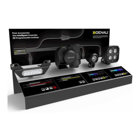
Interactive Dealer Display
CANsmart Display
What's In The Box?
Kit Contents
(a) Sheet Metal Base.................................................................Qty 1
(b) Display Wiring Harness (Lights).............................................Qty 1
(c) Self Tapping Screw...............................................................Qty 1
(d) Power Supply......................................................................Qty 1
(e) Battery Power Wiring Adapter................................................Qty 1
(f) Display Wiring Harness (Brake/Horn)......................................Qty 1
(g) Switch...............................................................................Qty 1
(h) M6 Screw...........................................................................Qty 2
(i) M6 Nut...............................................................................Qty 2
(j) Horn Mounting Bracket..........................................................Qty 1
(b)
(m)
(n)
Instruction Rev00
Thank you for choosing DENALI
We know you would rather be riding your bike than wrenching on it, so we go the extra
mile to make sure our instructions are clear and as easy to understand as possible. If
you have any questions, comments, or suggestions don't hesitate to give our gear
experts a call at 401.360.2550 or visit WWW.DENALIELECTRONICS.COM
Please Read Before Installing
DENALI products should always be installed by a qualified motorcycle technician. If
you are unsure of your ability to properly install a product, please have the product
installed by your local motorcycle dealer. DENALI takes no responsibility for damages
caused by improper installation. Caution: When installing electronics it is extremely
important to pay close attention to how wires are routed, especially when mounting
products to the front fender, front forks, or fairing of your motorcycle. Always be sure
to turn the handlebars fully left, fully right, and fully compress the suspension to
ensure the wires will not bind and have enough slack for your motorcycle to operate
properly.
Installation Tips
We strongly recommend using medium strength liquid thread locker on all screws,
nuts, and bolts. It is also important to ensure that all hardware is tightened to the
proper torque specifications as listed in your owner's manual. For included accessory
hardware please refer to the default torque specifications provided below. Inspect all
hardware after the first 30 miles to ensure proper torque specifications are
maintained.
Bolt Size
M3
M4
M5
M6
M8
M10
M12
Hardware Sizing Guide
Not sure what size bolt you have? Use this ruler to measure screws, bolts, spacers, etc.
Remember, the length of a screw or bolt is measured from the start of the "mounting
surface" to the end of the screw, so only include the screw head when measuring
countersunk screws.
0
10
mm
0
in
(a)
(h)
(k) (l)
(c)
(e)
(d)
(g)
(k) Brake Light Mounting Bracket................................................Qty 1
(l) M4 Screw............................................................................Qty 1
(m) Zip Tie Anchor....................................................................Qty 3
(n) Zip Tie...............................................................................Qty 6
(o) Decal.................................................................................Qty 4
(p) Backdrop Sign.....................................................................Qty 1
(q) Adhesive Square.................................................................Qty 4
Tools Required: 13mm Wrench, 10mm Wrench, 4mm Allen Key, 2.5mm
Allen Key, Phillips Head Screwdriver, Razor Blade, Rubbing Alcohol
DENALIELECTRONICS.COM
in-lbs
10.0 in-lbs
23.0 in-lbs
44.5 in-lbs
78.0 in-lbs
-
13.5 ft-lbs
-
30.0 ft-lbs
-
52.0 ft-lbs
20
30
40
50
1
2
(i)
(j)
(f)
(o)
(p)
ft-lbs
Nm
-
1.0 Nm
-
2.5 Nm
3.5 ft-lbs
5.0 Nm
6.5 ft-lbs
9.0 Nm
18.0 Nm
41.0 Nm
71.0 Nm
60
70
80
90
3
(q)
Advertisement

Summary of Contents for Denali CANsmart DNL.DSP.12000
- Page 1 401.360.2550 or visit WWW.DENALIELECTRONICS.COM Please Read Before Installing DENALI products should always be installed by a qualified motorcycle technician. If you are unsure of your ability to properly install a product, please have the product installed by your local motorcycle dealer. DENALI takes no responsibility for damages caused by improper installation.
- Page 2 1. Assembling The Display DENALIELECTRONICS.COM Cut Out From Decal 1.1 - Applying The Decals 1.2 - Mounting The Product & Switches Step One: Prepare the top surface of the sheet metal base (a) using Step One: Use a razor blade to cut out only the mounting holes highlighted rubbing alcohol.
- Page 3 3.1 - Wall Powered 3.2 - Battery Powered The DENALI 2.0 Interactive Dealer display can be plugged directly into an Step One: Plug the battery power adapter (e) into the display harness (b) 100v-240v outlet, or by using the included battery power wiring adapter, “power input”...
- Page 4 2. Wiring The Display DENALIELECTRONICS.COM To Switch (g) 12v DC Power (Output) To B6 Brake Light 12v DC Power (Input) Cut and Remove Spade Connectors. Instead use Posi-Locks from B6 2.1 - Connecting The B6 Brake Light 2.2 - Connecting The Switch Step One: Route the brake light harness (f) up through the wire pass Step One: Connect the smaller female spades to the male spades on the through on the display base (a).
Need help?
Do you have a question about the CANsmart DNL.DSP.12000 and is the answer not in the manual?
Questions and answers