Advertisement
Quick Links
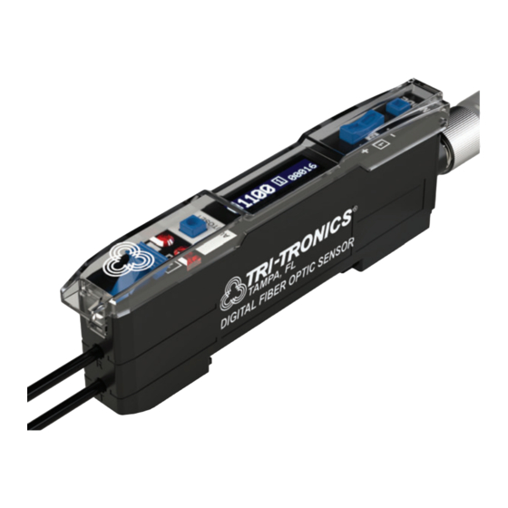
DFS21 - Instructions
How To Specify
1.
Select Sensor: DFS21
Dual Channel Digital
Fiber Optic Sensor
Features
WIDE VARIETY OF FIBERS
Visit www.ttco.com for full listing.
AUTOSET (l)
1. Push to perform AUTOSET.
2. Instantly optimizes when in Health Monitor Mode
3-WAY ROCKER SWITCH (q p)
1. Manually adjusts the threshold.+/-
2. Alters programming parameters.+/-
Hold to scroll for numeric values.
3. Press down on center to switch channels.
MODE (n)
Tap to access parameters.
Quick Start
The Digital Fiber Optic Sensor
a single push of a button; there is no guess work on the part of the operator. The sensor default settings* (Channel 1, Light State) will work
for most applications.
Follow the three step procedure below:
1.
Establish one of the following conditions:
Beam Make/Proximity - Reflect light off object.
Beam Break - Remove object from light beam path.
Beam Make
Proximity Mode
RECEIVER
LIGHT SOURCE
Beam Break
Retroreflective Mode
RECEIVER
LIGHT SOURCE
Opposed Mode
RECEIVER
LIGHT SOURCE
DFS Dual Channel Sensor
Channel 1 &
Channel 2
• Two Individual Thresholds
• Two Individual Outputs
2.
Select Light Source:
R = Red
I = Infrared
OBJECT
REFLECTOR
OBJECT
DETECTION PATH
OBJECT
DETECTION PATH
www.ttco.com • 800-237-0946
OR
Channel 1 &
Health Monitor
• Health Monitoring System
and Display
• Auto Signal Tracking
3.
Select Connection:
Blank = 6ft cable (1.8m)
C = 5-pin M8 connector
FIBER RELEASE CLAMP
Locks fibers in place.
DUAL CHANNEL OUTPUT LEDS
1. Channel 1 or 2 each illuminates solid when
2. Flashes when output is overloaded.
ADVANCED DIAGNOSTIC OLED DISPLAY
See next page for complete listing.
CONNECTION
5-Pin M8 connector or built-in cable.
is designed to provide reliable detection using fiber optic light guides. Sensor is adjusted by
2.
Tap AUTOSET (l) button:
Pressing the AUTOSET button
sets the sensors threshold to
the desired level.
3.
Verify setup on advanced diagnostic OLED display. If needed, the
threshold can be altered by tapping up or down on the threshold
adjust rocker.
Signal Level
Additional Features:
• Intuitive numerical/percentage diagnostic
OLED display
• Attractive 10mm wide housing
• Low power & wide operating voltage
• Advanced remote programming
• Six AUTOSET modes including window
• Crosstalk rejection between two sensors
without a wire
• Programmable output/input configurations
• High-speed, High-resolution, and Long-range
modes
• Combinable dual timers, and counters
• CE approved
DFS21
Example:
DFS21
Digital Fiber Optic Sensor
Light Source
Connection
output is ON.
*
Note: Consult all default settings on page 6.
Advanced Diagnostic OLED Display
Current
Channel
R
C
Threshold
1
Advertisement

Subscribe to Our Youtube Channel
Related Manuals for Tri-Tronics DFS21

Summary of Contents for Tri-Tronics DFS21
- Page 1 Additional Features: DFS21 - Instructions • Intuitive numerical/percentage diagnostic OLED display • Attractive 10mm wide housing DFS Dual Channel Sensor • Low power & wide operating voltage • Advanced remote programming • Six AUTOSET modes including window • Crosstalk rejection between two sensors without a wire •...
-
Page 2: Using Autoset
Programming Using AUTOSET Switch between Screens 1 and 2 by pressing straight down on the The DFS threshold is set automatically by 3-way toggle switch. pressing the AUTOSET button. There are six different ways the sensor determines the threshold. The user first must determine which type of setup mode is appropriate for the When using DUAL CHANNEL: application. - Page 3 Detect Mode SENSOR Sensor output activates or deactivated when received light intensity is over the threshold. Not available when LIGHT ON input function is set to Remote Dark On. Light On (LO): Output activates when received light intensity is over the Detect Mode: OBJECTS threshold.
- Page 4 The following are system wide perameters that can only be adjusted in Channel 1. (Change channels by pressing straight down on the rocker switch if necessary). Response Time Fastest Select which mode that best fits the performance need of your application. Sensor speed, range, and sensitivity Speed are optimized for best performance.
- Page 5 Input Functions Select input to be performed: Remote set: An AUTOSET function is performed when input wire is transitioned from idle to Input Function: active and returned. Note: input wire can be used in addition to the AUTOSET button. Remote Set Remote command: Sensor parameters can be adjusted via defined pulses.
- Page 6 The DFS21 includes a new feature to address this issue. We use a unique algorithm to track how far above (+Margin)
-
Page 7: Health Monitor
Remote Command Setting Option Icon Pulse Notes Sequence Programming AUTOSET Channel 1 1 - - - A single pulse initiates AUTOSET. An additional pulse command is required Channel 2 2 - - - to complete AUTOSET for two-point In Remote Command Mode a limited set of options and dynamic modes. -
Page 8: Specifications
• HS, STD, HR, LR, ULR (15.635µs) • IR = 880nm (Use glass fibers with Ø2.2mm Product subject to change without notice • Asynchronous crosstalk enabled (31.25µs) connection only). Dimensions DFS21 Digital Fiber Optic Sensor 3.58" [90.9mm] CLEAR COVER (SEE DETAIL) 35mm DIN RAIL MOUNTING...
Need help?
Do you have a question about the DFS21 and is the answer not in the manual?
Questions and answers