
Related Manuals for BNC 685 Series

Summary of Contents for BNC 685 Series
- Page 1 Model 685 Performance AWG User Manual (Active Technology MODEL 685 Series) Rev 1.0, June 2021...
-
Page 2: Table Of Contents
Summary CONTACTING BERKELEY NUCLEONICS ..............ERROR! BOOKMARK NOT DEFINED. GENERAL SAFETY SUMMARY ..........................7 ..........................7 VOID IRE OR ERSONAL NJURY Use Proper Power Cord ............................7 Ground the Product ............................... 7 Observe All Terminal Ratings ..........................7 Power Disconnect ..............................7 Do Not Operate Without Covers ........................... - Page 3 INSTRUMENT OVERVIEW ............................. 21 685-2C ..............................21 RONT ANEL 685-4C ..............................22 RONT ANEL 685-8C ..............................23 RONT ANEL Analog Outputs ..............................24 Marker Outputs ..............................24 Trigger Inputs ..............................24 Soft keyboard and rotary knob ........................... 26 Numeric Keypad ..............................27 685-2C ..............................
- Page 4 Reference Clock Input Connector ........................47 Reference Clock Output Connector ........................47 External Clock Input Connector ........................... 48 Sync Clock Output Connector ..........................48 Digital Output connector ............................ 48 Sync In / Sync Out Connectors ..........................48 PREDEFINED WAVEFORMS ..........................49 List and parameters of predefined waveforms ....................
- Page 5 ..............................86 AFETY OMPLIANCE ............................87 NVIRONMENTAL OMPLIANCE Rev 1.1 Berkeley Nucleonics Corporation info@berkeleynucleonics.com | www.berkeleynucleonics.com 2955 Kerner Blvd, San Rafael, CA 94901 | 800-234-7858...
-
Page 6: Contacting Berkeley Nucleonics
Operator’s Manual Simple AFG Application This manual is copyright by Berkeley Nucleonics Corporation (BNC) and all rights are reserved. No portion of this document may be reproduced, copied, transmitted, transcribed, stored in a retrieval system, or translated in any form or by any means such as electronic, mechanical, magnetic, optical, chemical, manual or otherwise, without written permission of Berkeley Nucleonics Corporation. -
Page 7: General Safety Summary
Operator’s Manual Simple AFG Application General Safety Summary Review the following safety precautions to avoid injury and prevent damage to this product or any products connected to it. To avoid potential hazards, use this product only as specified. Only qualified personnel should perform service procedures. To Avoid Fire or Personal Injury Use Proper Power Cord Use only the power cord specified for this product and certified for the country of use. -
Page 8: Safety Requirements
Operator’s Manual Simple AFG Application Safety Requirements This section contains information and warnings that must be observed to keep the instrument operating in a correct and safe condition. You are required to follow generally accepted safety procedures in addition to the safety precautions specified in this section. Safety Symbols Where the following symbols appear on the instrument’s front or rear panels, or in this manual, they alert you to important safety considerations. - Page 9 Operator’s Manual Simple AFG Application CAUTION The CAUTION sign indicates a potential hazard. It calls attention to a procedure, practice or condition which, if not followed, could possibly cause damage to equipment. If a CAUTION is indicated, do not proceed until its conditions are fully understood and met. WARNING The WARNING sign indicates a potential hazard.
-
Page 10: Environmental Considerations
Operator’s Manual Simple AFG Application Environmental considerations Product End-of-life Handling Observe the following guidelines when recycling an instrument or component. Equipment Recycling Production of this equipment required the extraction and use of natural resources. The equipment may contain substances that could be harmful to the environment or human health if improperly handled at the product’s end of life. -
Page 11: Preface
The easiest touch screen display interface allows to create waveforms scenarios, only in few screen touches. The Model 685 series offers premium signal integrity thanks to the 16 bit resolution DAC. For single ended Models the output signal can reach up to 5 Volts pk-pk into 50 Ohm and a total voltage window of 10 Volts into 50 Ohm with an hardware offset of ±2.5 Volts into 50 Ohm. -
Page 12: Recommended Options And Accessories
GPIB and USBTMC Ports for Remote Control O = Options, A = Accessories Key features The following list describes some of the key features of the MODEL 685 series • High resolution, high sampling rate in Baseband Mode: 16 Bits, 6.16GS/s. -
Page 13: Mechanical Characteristics
Operator’s Manual Simple AFG Application Simple touch screen user interface to create complex waveforms scenarios just in few screen • touches. Large 7 inch, 1024x600 capacitive touch LCD. • Touchscreen or Keypad data entering. • • Windows 10 operating system. USB and LAN interfaces. -
Page 14: Environmental Requirements
Operator’s Manual Simple AFG Application Left and right side: 150 mm (5.9 in) • • Bottom: 20 mm (0.8 in) Rear: 75 mm (3 in) • CAUTION. Ensure that the equipment is positioned in a way that the disconnecting device can be readily accessible. -
Page 15: Cleaning
Operator’s Manual Simple AFG Application Power Consumption Model 685-2C Maximum: 100W Model 685-4C Maximum: 200W Model 685-8C Maximum: 300W WARNING - Electrical Shock Hazard Only use the power cord provided with your instrument Cleaning WARNING. To avoid personal injury, power off the instrument and disconnect it from line voltage before performing any other following procedures. -
Page 16: Installing Your Instrument
Operator’s Manual Simple AFG Application shows visible damage or has been subjected to severe transport stresses. Proper use of the instrument depends on careful reading of all instructions and labels. WARNING. Any use of the instrument in a manner not specified by the manufacturer may impair the instrument’s safety protection Installing your instrument Unpack the instrument and check that you received all items listed in the Package Contents paragraph. -
Page 17: Obtaining The Latest Version Releases
Operator’s Manual Simple AFG Application CAUTION. Do not short output pins or apply external voltages to Output connectors. The instrument may be damaged. CAUTION. Do not apply excessive inputs over ±15 Vpk to Trigger Input connector. The instrument may be damaged. -
Page 18: Usb Rev 1.1 Pen Drive And Recovery Procedure
Operator’s Manual Simple AFG Application 4) When the application has been installed, press the “Close” button to continue. USB Pen Drive and Recovery Procedure In case of software failure or corrupted applications, it’s possible reinstall the full factory image of the software using the 32 GB Usb Pen Drive included in the package. -
Page 19: Recovery Procedure
Operator’s Manual Simple AFG Application Note: The procedure completely formats the SSD of the instrument so remember to save all important data (Configuration files, Arbitrary User Waveform files…) in an external device because all the current settings will be lost when the Recovery Procedure is launched. Note: If two SSD are mounted on the instrument remember to leave only the one on which you want to launch the procedure, the other must be removed. - Page 20 Operator’s Manual Simple AFG Application 5) Enter the code "1234" to confirm the execution of the recovery procedure. 6) Once the procedure is complete, press enter to shut down the instrument. 7) Remove the Recovery USB Pen Drive and power ON the instrument. Follow the instructions at point 2) to access the Boot menu and select SATA SSD source.
-
Page 21: Instrument Overview
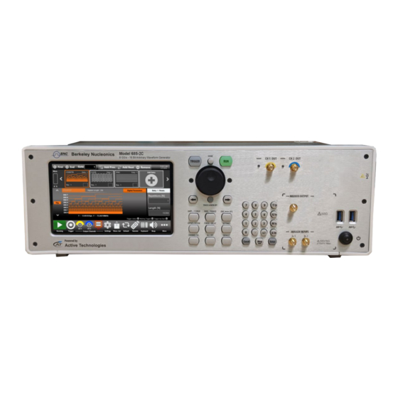
Operator’s Manual Simple AFG Application Instrument Overview Front Panel Model 685-2C Single ended analog outputs Power on/off Soft Keyboard and button, 7” Capacitive Numeric Rotary Knob Trigger In and 2 USB ports Touch Screen Keypad Marker Output Rev 1.1 Berkeley Nucleonics Corporation info@berkeleynucleonics.com | www.berkeleynucleonics.com 2955 Kerner Blvd, San Rafael, CA 94901 | 800-234-7858... -
Page 22: Front Panel 685-4C
Operator’s Manual Simple AFG Application Front Panel Model 685-4C Single ended analog outputs Soft Keyboard and Trigger In Rotary Knob Numeric Marker 7” Capacitive Keypad 2 USB 3.0 ports, Outputs Touch Screen Power ON/OFF button Rev 1.1 Berkeley Nucleonics Corporation info@berkeleynucleonics.com | www.berkeleynucleonics.com 2955 Kerner Blvd, San Rafael, CA 94901 | 800-234-7858... -
Page 23: Front Panel 685-8C
Operator’s Manual Simple AFG Application Front Panel Model 685-8C Single ended analog outputs 2 USB 3.0 ports, Power on/off button Numeric Keypad 7” Capacitive Soft Keyboard and Trigger In and Touch Screen Rotary Knob Marker Outputs The front panels of the Model 685 2C/4C/8C differ from that shown in the picture above because they have twice the SMA analog output connectors because each output channel has two complementary outputs (+ and -). -
Page 24: Analog Outputs
Operator’s Manual Simple AFG Application Analog Outputs The MODEL 685 instrument series has 2/4/8 analog output channels, each one is single-ended or differential (depending on the Model) and the connector type is a standard SMA. Marker Outputs Each Marker Out is a digital output channel that can generate programmable digital patterns synchronous to the analog outputs. - Page 25 Operator’s Manual Simple AFG Application Rev 1.1 Berkeley Nucleonics Corporation info@berkeleynucleonics.com | www.berkeleynucleonics.com 2955 Kerner Blvd, San Rafael, CA 94901 | 800-234-7858...
-
Page 26: Soft Keyboard And Rotary Knob
Operator’s Manual Simple AFG Application Soft keyboard and rotary knob Most of the buttons you use with Simple AFG application are virtual ones on the touchscreen, but a few physical buttons control basic functions, such as the setting of amplitude, offset, frequency, etc. A physical numeric keypad is available on the front-panel and it can be used instead of the virtual numeric pad. -
Page 27: Numeric Keypad
Operator’s Manual Simple AFG Application Button Description HOME If you are in a sub-menu page, use this button to return to the main page. TRIGGER Use this button to send an internal trigger to the instrument. If the button is on and green the Use this button to start and stop the signal generation. -
Page 28: Rear Panel 685-2C
Operator’s Manual Simple AFG Application When you select a parameter on the user interface, if you press a Unit Measure Range button it will automatically update the available range allowed for that parameter. Unit Measure Range Button Unit Measure Range Tera / pico Giga / nano Mega / micro... -
Page 29: Rear Panel 685-4C
Operator’s Manual Simple AFG Application Rear Panel Model 685-4C The callouts on this image gives the description of the corresponding connectors: • 1 Ref Clk In: 5 to 200 MHz 1 10_MHz (100MHz Optional) Ref Clock Output • • 1 External Modulation Input •... -
Page 30: Rear Panel 685-8C
Operator’s Manual Simple AFG Application Rear Panel Model 685-8C 2 Slots for Removable 4 Digital Output Connectors: Pod A, Pod B, Pod C, Pod D 1 Ref Clk In: 5 to 200 MHz • • 1 10_MHz (100MHz Optional) Ref •... -
Page 31: External Modulation Input Connector
Operator’s Manual Simple AFG Application External Modulation Input Connector The MODEL 685 series instrument has an input connector to receive an external analog signal that is used as modulating source. When the selected Run Mode is “Modulation” and the source is “External”... -
Page 32: Introduction
Simple AFG Software The MODEL 685 series instrument includes a 7” capacitive touch screen and an easy touch user interface based on a Microsoft Windows 10 platform. You can control instrument operations using one or all of the following entering methods: •... -
Page 33: User Interface Description
Operator’s Manual Simple AFG Application User Interface Description The Simple AFG software environment provides an easy access to all instrument functionalities and parameters. Waveform Parameters Area Graph Area Channel Information Command AFG user interface consists of four main elements: Waveform Parameters Area: it contains all the waveform settings. It is composed by the •... - Page 34 Operator’s Manual Simple AFG Application If you use the Swipe left or right gesture on the Graph Area you can switch between the Output Channel 1 and Output Channel 2 page. If you use the Swipe left or right gesture on the Waveform Parameter Area you can switch the page between Carrier tab and the Secondary tab.
-
Page 35: Waveform Parameters Area
Operator’s Manual Simple AFG Application Waveform Parameters Area This section is composed by two tabs: the Carrier tab and the Secondary tab. In the Carrier tab it is possible to define the Run Mode, of the Carrier Waveform and its •... - Page 36 Operator’s Manual Simple AFG Application 1. Parameter Name and Value: This area of the virtual keyboard displays the parameter name, value and unit of measure. 2. Numeric Keypad: this area contains the keys to edit the number that will be displayed in the area 1.
-
Page 37: Graph Area
Operator’s Manual Simple AFG Application 7. The horizontal scrollbar allows to change quickly the selected value. The position specifies the value between the allowed minimum and the maximum. The increment/decrement value entered by the rotary knob or by the scrollbar are applied to the instrument on the fly. -
Page 38: Channel Information
Operator’s Manual Simple AFG Application Channel Information This area displays the channel name and a list of all the main current channel settings: the selected waveform type, the Modulation / Sweep / Burst mode, the Generation mode, the channel status and the Trigger Source. - Page 39 Operator’s Manual Simple AFG Application Copy Ch1 (Ch N) Button –This button copies all the channel settings to the other channels. When you press the button a dialogue window appears to Confirm or Cancel the operation. As example on four channel Models, you can copy the channel 1 into channel 2,3,4 or the channel 2 into channel 1,3,4 depending on the current selected one.
- Page 40 Operator’s Manual Simple AFG Application More Button Menu Items Description Exit Button – This button closes the application. Change Application –This button switches from AFG to TrueARB or to SPG application (when a -PAT license is available). Minimize Button –This button minimizes the application screen; in this way you can access to Windows OS.
-
Page 41: Input / Output Channels
Operator’s Manual Simple AFG Application Input / Output Channels The MODEL 685 has 2/4/8 independent analog channels. Each channel can be single-ended or differential (depending on the Model) and it is available on a SMA connector (or two SMA connectors for the differential output) located in the front instrument panel (CH1, Ch2, …, CHn output). -
Page 42: Amplitude
Operator’s Manual Simple AFG Application The output signal levels displayed by the Simple AFG UI text are calculated for the specified source and load impedances that by default are 50 Ohm. To change the expected load and source impedance please refer to the Channel Settings. Amplitude The amplitude can be represented in three different formats that can be selected by opening the menu beside the amplitude label:... -
Page 43: High Level [V]
Operator’s Manual Simple AFG Application High Level [V] It defines the maximum level of the waveform expressed in Volts Low Level [V] It defines the minimum level of the waveform expressed in Volts These parameters are available for all function excepts the DC level that is identified only by the Offset parameter. -
Page 44: Main Channels Horizontal Parameter
Operator’s Manual Simple AFG Application Main Channels Horizontal parameter The horizontal parameters can control the frequency, the phase and the shape of the waveform. The set of available parameters depend on the selected waveform. Frequency [Hz] / Period [s] This parameter defines the frequency or the period of the generated waveform. This parameter is available for all the functions except DC Level and Noise. -
Page 45: Auxiliary Channels
Operator’s Manual Simple AFG Application Auxiliary Channels Rev 1.1 Berkeley Nucleonics Corporation info@berkeleynucleonics.com | www.berkeleynucleonics.com 2955 Kerner Blvd, San Rafael, CA 94901 | 800-234-7858... -
Page 46: Marker Outputs
Operator’s Manual Simple AFG Application Marker Outputs The Marker Out generates a digital pulse synchronous with the waveform or with the modulating function depending on the Run Mode. Its impedance is 50 Ohm and the output voltage amplitude ranges from -0.5 V to 1.65 V into 50 Ohm load. -
Page 47: External Modulation Input Connector
FSK, PSK: 0V÷3.3V with 1.65V fixed threshold Reference Clock Input Connector The MODEL 685 series instrument can use an external clock source to generate the sampling clock frequency. This feature allows to synchronize the generator with an external clock and the frequency range is 5 MHz to 200 Mhz. -
Page 48: External Clock Input Connector
Operator’s Manual Simple AFG Application Reference Clock Output Value Connector 1 SMA on the Rear Panel Output impedance 50Ω, AC coupled Output Frequency 10MHz (100 MHz optional) External Clock Input Connector This connector input gives the User the possibility to feed directly a sampling clock for the System. This Clock bypasses the internal Clock Synthesizer of the instrument. -
Page 49: Predefined Waveforms
Operator’s Manual Simple AFG Application Predefined Waveforms The Simple AFG application provides 13 predefined functions each of them described by its own set of parameters. It is also available the Arbitrary waveform that allows to load a waveform from a file or from remote. - Page 50 Operator’s Manual Simple AFG Application AM, FM, Waveform Parameters PM, PSK, Sweep Burst Sine Amplitude, Offset, √ √ √ Frequency, Phase Square Amplitude, Offset, √ √ √ Frequency, Phase Ramp Amplitude, Offset, √ √ √ Frequency, Phase, Symmetry Pulse Amplitude, Offset, Frequency, Phase, Duty √...
- Page 51 Operator’s Manual Simple AFG Application AM, FM, Waveform Parameters PM, PSK, Sweep Burst DC Level Offset Gaussian Amplitude, Offset, √ √ √ Frequency, Phase Lorentz Amplitude, Offset, √ √ √ Frequency, Phase Exponential Rise Amplitude, Offset, √ √ √ Frequency, Phase Exponential Decrease Amplitude, Offset,...
- Page 52 Operator’s Manual Simple AFG Application You can assign the “Arbitrary” waveform using the “Import” button in the command bar. For more information refer to the “Import from File” paragraph. By default, the “Arbitrary” waveform is a cosine function. Note: When Arbitrary waveform is selected the amplitude and offset of the original waveform are lost because the waveform in normalized.
-
Page 53: Run Mode
Operator’s Manual Simple AFG Application Run Mode On the Carrier tab pressing the “Run Mode” button a menu opens showing all possible choices for the Run Mode. If “Modulation”, “Sweep” or “Burst” is selected the software moves directly on the secondary tab that takes the name of the selected Run Mode. -
Page 54: Continuous
Operator’s Manual Simple AFG Application Continuous In the Continuous mode when the Run/Stop button is pressed the waveform is reproduced continuously until the Run/Stop button is pressed again or Waveform / Run Mode is changed. Marker Out behaviour in Continuous Run Mode In Continuous mode, the Marker Out generates a pulse with a duty cycle of about 50% (Automatic width mode) or a User predefined width (Manual width mode) at the beginning of each period. -
Page 55: Modulation
Operator’s Manual Simple AFG Application Marker out frequency = Carrier frequency / 8 when: 385MHz < Carrier frequency <= 770 MHz • • Marker out frequency = Carrier frequency / 16 when: 770MHz < Carrier frequency <= 1.54GHz Marker out frequency = Carrier frequency / 32 when: 1.54GHz < Carrier frequency <= 2 GHz. •... - Page 56 Operator’s Manual Simple AFG Application The modulation types are: Amplitude Modulation (AM) • Frequency Modulation (FM) • • Phase Modulation (PM) Frequency Shift Keying (FSK) • Phase Shift Keying (PSK) • • Pulse Width Modulation (PWM) The PWM modulation is the only modulation supported by the Pulse waveform. The types of modulation are explained in detail in the following sections of this chapter.
-
Page 57: Marker Out Behaviour In Modulation Run Mode
Operator’s Manual Simple AFG Application The modulation Shapes (when available) can be: • Sine • Square Triangle • • Increase Ramp Decrease Ramp • Noise • • Arbitrary: it allows to load a Modulating Waveform from file. For the file specification please refer to the “Import from File”... -
Page 58: Modulation General Parameter
Operator’s Manual Simple AFG Application Marker out (blue, top) synchronous with the modulating waveform of the AM (red, bottom) in Manual width mode Modulation General Parameter • Frequency [Hz]: it defines the modulating frequency. It can vary between 500uHz and 61MHz. Source: the source can be Internal or External. -
Page 59: Sweep
Operator’s Manual Simple AFG Application Frequency Shift Keying (FSK): this modulation is a 2 level FSK. The carrier frequency switches • between the initial carrier frequency and the initial carrier frequency + Hop Frequency [Hz]. It is available for all functions except for the Pulse, Double Pulse, DC level and Noise. ��������������������... -
Page 60: Sweep Mode
Operator’s Manual Simple AFG Application Sweep Mode Touching the Sweep Mode button, a menu opens that gives the possibility to choose a sweep profile among the following: Linear: the frequency increases and decreases linearly. • Logarithm: the frequency increases and decreases following a logarithmic function. •... -
Page 61: Sweep Trigger Mode
Operator’s Manual Simple AFG Application Return Time [s]: controls the time to decrease the frequency from the Stop Frequency back to • the Start Frequency. �������� ���� ���� �������� ���� ���� + ������������ ���� �������� ���� ���� + ������������ ���� �������� �������� ���� ���� ≤ 2000 ���� Note: the time parameters must meet the following conditions: Step Number: selects the number of frequency steps of the Upstair Sweep mode. -
Page 62: Burst
Operator’s Manual Simple AFG Application Marker out (blue, top) synchronous with the sweep (red, bottom) in Manual width mode (only for Repeat mode) Burst In Burst mode a waveform is repeated a predefined number of times or until the Trigger signal is at High Level depending on the selected Burst Type. -
Page 63: Burst Mode
Operator’s Manual Simple AFG Application Burst Mode The burst mode allows to define the behaviour of the instrument after the Trigger reception. Touching the “Mode” button the following menu opens and it is possible to select the burst type. • 1 Cycles: the instrument waits for a Trigger. - Page 64 Operator’s Manual Simple AFG Application In this case the user can set which voltage level will be generated between one burst and another: the carrier’s first or last sample. Exponential Rise Carrier, 1-Cycle Burst Mode, Wait Trigger On First Sample Exponential Rise Carrier, 1-Cycle Burst Mode, Wait Trigger On Last Sample Rev 1.1 Berkeley Nucleonics Corporation...
-
Page 65: Marker Out Behaviour In Burst Run Mode
Operator’s Manual Simple AFG Application Marker Out behaviour in Burst Run Mode In this Run Mode, the Marker Out generates a pulse with a duration equal to the duration of the burst sequence or to the gate time duration (time when the Trigger signal is at High level). So the marker’s width parameter is meaningless while the maximum marker’s skew is 2.25us. -
Page 66: Main Command Button Description
Operator’s Manual Simple AFG Application Main Command Button Description Save Settings The button “Save Settings” in the “More” menu allows to save the current instrument settings called “memory”. In the relative dialogue box, you can save a new memory entry or overwrite an existing one. -
Page 67: Load Settings
Operator’s Manual Simple AFG Application Load Settings Touching the “Load Settings” button in the “More” menu, a page will open showing the list of all the saved memories. Selecting a memory entry, the current instrument settings will be immediately updated with those of the memory entry. The buttons have the same functionality explained in the “Save Settings”... -
Page 68: Remote Control
Operator’s Manual Simple AFG Application Remote Control The “Remote” button located in the Command Bar opens the page of the SCPI server. In that page there is the list of all the commands received by the SCPI server and its replies. If the text of the command is displayed in green it means that the command is correct and it has been accepted by the... -
Page 69: Gpib Control
Operator’s Manual Simple AFG Application GPIB and USBTMC Connector (optional) GPIB control Follow these instructions to setting up the instrument for remote communication using the GPIB (General Purpose Interface Bus) interface: • Connect one side of a GPIB cable to the GPIB port of the Model 685 (on the rear panel), and your GPIB controller on the other side. -
Page 70: Usbtmc Control
Operator’s Manual Simple AFG Application USBTMC control The USBTMC protocol allows USB devices to communicate using IEEE488 style messages. This lets you run the SCPI commands using USB hardware. Connect an appropriate USB cable (A MALE - B MALE) between the USBTMC port of the Model •... -
Page 71: Channels And Device Setting
Operator’s Manual Simple AFG Application Now you can send the SCPI commands to the AWG5000 resource using the NI Visa Test Panel. • Channels and Device Setting Press this button to open the settings page composed by N +1 number of tabs, N for each Channel of the instrument and one for the Device. - Page 72 Operator’s Manual Simple AFG Application Baseline Defines the DC offset value added to the output signal respect to the ground level. Offset[V] The range is between -2.5 V to 2.5 V on 50 Ohm load and it depends on the selected load impedance (i.e.
-
Page 73: Device Settings
Operator’s Manual Simple AFG Application Device Settings The “Device Settings” page contains the general setting of the instrument, such as the clock source and the Marker Out setting. Touching the “Settings” button in the menu bar or the “SETTINGS” button on the keyboard the channel settings page open. -
Page 74: Timing Settings
Operator’s Manual Simple AFG Application Device Setting Description Timing Use this group of parameters to specify the clock source as Internal or External (REF CLK or EXT CLK), to set the external reference clock’s frequency and to enable the Sync Clock Out (see the Timing table below). Trigger IN Use this group of parameters to define the Trigger In behaviour (see the table below). -
Page 75: Trigger In Settings
Operator’s Manual Simple AFG Application In Settings Trigger The Trigger In settings parameters are located in the Device Setting page. These parameters are shared by all channels of the instrument. Trigger In Settings: 2 Channels Model Trigger In Setting Description Source Button: the Trigger event is provided to the instrument by pressing the Trigger button on the keyboard or the Trigger button on the menu toolbar... -
Page 76: Marker Out Settings
Operator’s Manual Simple AFG Application Interval [s] Set the timer count interval. It has effect only when the selecting trigger Source is Timer. The Interval range is from 10.4ns to 100s. Slope The Slope can be positive, negative or both. When positive is selected the trigger is detected when the signal on the Trigger In 1 SMA connector crosses the threshold from low to high. - Page 77 Operator’s Manual Simple AFG Application Marker Out Settings: 2 Channels Model Marker Out Settings: 8 Channels Model Note: for 4 and 8 channels Models press the Marker 1,…Marker 4 tab to visualize the corresponding marker’s settings. Marker Out Setting Description High Level [V] Specifies the Marker high level Voltage.
- Page 78 Operator’s Manual Simple AFG Application State Enables or disables the Marker Out. When the Marker Out is disabled it is forced to 0V. Note: using some Waveforms Carrier or setting specific Run Modes it may happen that the marker has no meaning. In that case the state button will be disabled.
-
Page 79: Import From File
Operator’s Manual Simple AFG Application Import from File The Import page allows to load a waveform from a file and assign it to the Carrier waveform or to the Modulation profile or to the Sweep profile. This page opens by touching the Import button Once the waveform has been imported it will be available by choosing “Arbitrary”... - Page 80 Operator’s Manual Simple AFG Application Offset and Amplitude When a waveform is imported from a file its original amplitude and Range offset are lost because the waveform in normalized during the importing process. Anyway, the amplitude and offset of the normalized waveform can be redefined as for any predefined waveforms.
- Page 81 Operator’s Manual Simple AFG Application 4. Set the Modulation parameters as preferred 5. Press Run/Stop button to start the generation. Rev 1.1 Berkeley Nucleonics Corporation info@berkeleynucleonics.com | www.berkeleynucleonics.com 2955 Kerner Blvd, San Rafael, CA 94901 | 800-234-7858...
-
Page 82: Channels Coupling
Operator’s Manual Simple AFG Application Channels Coupling In electronics design and testing, it is sometimes required to have two synchronized clock signals that are related by a frequency ratio: one clock needs to maintain a certain frequency ratio with respect to the other clock. - Page 83 Operator’s Manual Simple AFG Application Swipe up or down to select which channel to couple to the Channel 1. • • ON/OFF button: enables or disables the channel coupling. Reset: resets the Ratio and Offset parameters to their default values (1 and 0). •...
- Page 84 Operator’s Manual Simple AFG Application Frequency range will be recalculated and since the Square cannot reach 1 GHz of maximum frequency the frequency coupling will be disabled. • If you press the Copy Ch N Button while the coupling channel is active, only the parameters that are not coupled will be copied to the other channels.
- Page 85 Operator’s Manual Simple AFG Application Rev 1.1 Berkeley Nucleonics Corporation info@berkeleynucleonics.com | www.berkeleynucleonics.com 2955 Kerner Blvd, San Rafael, CA 94901 | 800-234-7858...
-
Page 86: Certifications
Operator’s Manual Simple AFG Application Certifications Berkeley Nucleonics certifies compliance to the following standards as of the time of publication. Please see the EC Declaration of Conformity document shipped with your product for current certifications. EMC Compliance EC DECLARATION OF CONFORMITY - EMC The instrument meets intent of EC Directive 2014/30/EU for Electromagnetic Compatibility. - Page 87 Operator’s Manual Simple AFG Application • Mains Supply Connector: Overvoltage Category II, instrument intended to be supplied from the building wiring at utilization points (socket outlets and similar). • Measuring Circuit Terminals: No rated measurement category. Terminals not intended to be connected directly to the mains supply.
Need help?
Do you have a question about the 685 Series and is the answer not in the manual?
Questions and answers