Table of Contents
Advertisement
Quick Links
Advertisement
Table of Contents

Subscribe to Our Youtube Channel
Summary of Contents for FETtec FC F7
- Page 1 FETtec FC F7 Manual Page 1...
-
Page 2: Table Of Contents
Introduction ..........................3 Features ............................3 Safety warning ..........................4 Recommended steps for installation of the FETtec FC F7 ............4 Connection Diagram ........................5 Connection layout top ....................... 5 Connection layout bottom ......................6 FETtec FC F7 version 1.2 ......................7 ESC connection diagram ...................... -
Page 3: Introduction
Introduction Thank you for purchasing the FETtec FC F7. This is a KISS licensed F7 Flight-controller Features • KISS FC v2 firmware (FETtec Alpha FC firmware flashable) • F7 Processor ◦ STM32F7RET6 @ 216MHz ◦ MPU6000 • Supply voltage 6-27V (2S-6S Lipo) •... -
Page 4: Safety Warning
Install the FC in your copter (see Connection diagrams for correct wiring and installation) • Make sure everything is connected properly and check without propellers • Connect to FETtec Configurator to proceed with final configuration of the FETtec FC F7 Page 4... -
Page 5: Connection Diagram
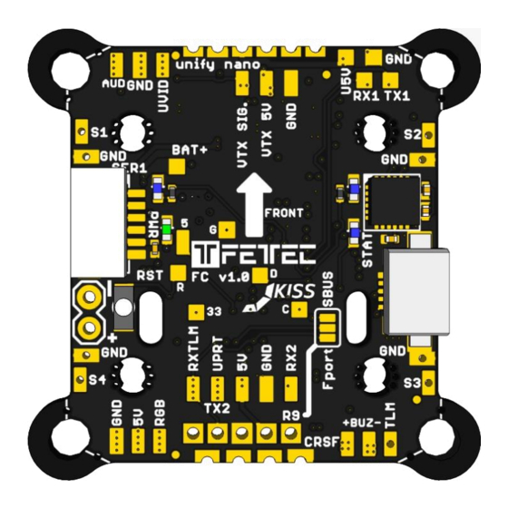
Connection Diagram Connection layout top 6 pin connector (SER1): • RX1: for digital FPV systems or other functions configurable in GUI (same for VCS/TX3) • TX1: for smart audio / tramp configuration or TX for digital FPV systems • RGB LED: PWM signal pin to control WS2812 LEDs or similar (configurable in GUI) •... -
Page 6: Connection Layout Bottom
Connection layout bottom 8 pin ESC connector: • BAT+: Battery voltage out to supply FC power • • ESCTLM/Onewire: ESC Telemetry signal to FC or Onewire signal pin (depending on configuration) • Signal 1-4: ESC signal output for each ESC Receiver connector: •... -
Page 7: Fettec Fc F7 Version 1.2
FETtec FC F7 version 1.2 Page 7... -
Page 8: Esc Connection Diagram
ESC connection via 8 pin connector For easy ESC connection via 8 pin cable FETtec FC F7 to FETtec 4in1 ESC 35A (same for FETtec 4in1 ESC 45A), cable included with FETtec ESCs. Any other ESC is usable (please make sure the signal pinout is correct, otherwise change... -
Page 9: Receiver Connection (Rx)
Receiver connection (RX) Top & Bottom connectors for receivers (bottom connector JST-SH-1mm 4-pin) TBS Crossfire Crossfire nano connection cable connection 2,54mm pinheader connection Page 9... -
Page 10: Sbus Receiver / Frsky R-Xsr
SBUS receiver / FrSky R-XSR Page 10... -
Page 11: Vtx Connection (Unify Nano)
VTX connection (Unify nano) Page 11... -
Page 12: Camera Connection
Camera connection Notes: • RX and TX connection is only for cameras that support serial • 5V (U5V) and Video (UVID) are only for use with a mounted unify PRO nano or unify PRO nano 32 Resetbutton Resets the FC to the preflashed bootloader Page 12... -
Page 13: Fc Configuration
Install KISS GUI • Connect COM port • To update the FETtec FC firmware please use the KISS GUI and choose FETTEC KISS • Configuration can be made in the KISS GUI, settings are in the advanced tab Page 13... -
Page 14: Fettec Alpha Fc Firmware
FETtec Alpha FC firmware The FETtec FC F7 is compatible with FETtec Alpha FC firmware. 1. Open FETtec Toolset https://gui.fettec.net and choose ALPHA Configurator. 2. Connect the FETtec FC via USB. 3. Open the ALPHA Configurator and select open port. Choose the serial port on which the FC shows up and press connect. - Page 15 5. “Select new firmware to flash”. We always recommend flashing the latest available firmware. 6. Confirm to flash FETtec ALPHA firmware by pressing “OK” Page 15...
- Page 16 7. FC firmware update is done! The FC needs a restart after that, therefore the com port is requested to be selected and connected again Now you can customize everything in the GUI according to your wishes. Please connect everything like described in the manual of the FC. The receiver signal will get auto detected (supported systems are Frsky Sbus+S-Port, CRSFv2 and CRSFv3 and Ghost).
-
Page 17: Get Back To Kiss
Get back to KISS If the FETtec Alpha FC firmware is flashed on your FC and you want to get back to KISS firmware, follow these steps: 1. Open FETtec Toolset https://gui.fettec.net/ 2. Connect the FETtec FC via USB. 3. Press the reset button once 4. - Page 18 7. Flashing to KISS FC firmware done. Page 18...
-
Page 19: Firmware Updates On Fettec Alpha Fc Firmware
Firmware updates on FETtec Alpha FC firmware For firmware updates it is the same procedure as flashing the FETtec Alpha FC firmware. Connect FC via open port and choose “Firmware”. Now you can flash the latest firmware update via “Select new firmware to flash” or choose “Flash local file”. -
Page 20: Settings In Fettec Alpha Fc Firmware
Settings in FETtec Alpha FC firmware You can set up the FC according to your wishes in the ALPHA Configurator. All functions are explained in the respective category. For more information and help use the FETtec Alpha FC firmware manual available at www.fettec.net/download Page 20... -
Page 21: Display Connection
Display connection I2C O-LED to FETtec FC F7 I2C O-LED display can be used to show the OSD menu and telemetry in order to be able to set up settings without computer or FPV goggles (FPV OSD). The I2C connection will block serial 3 which is mostly used for digital OSD or analog VTX control (VCS). -
Page 22: Dimension (In Mm)
Dimension (in mm) Dimensions 35x30mm without 30x30 corners ◦ 20x20mm (with breakable holes M2 to M3) ◦ 30x30mm hole distance useable (breakable 30x30mm corners) • Overall height: 7,9mm • Weight: 5,37g • Connector type: JST-SH-1mm Page 22...
Need help?
Do you have a question about the FC F7 and is the answer not in the manual?
Questions and answers