Table of Contents
Advertisement
Quick Links
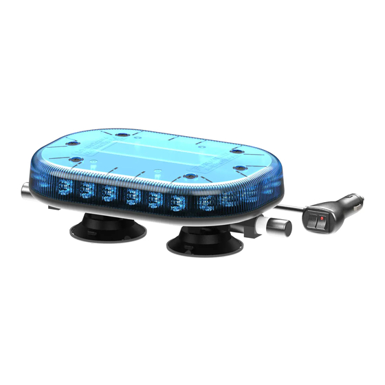
Installation and Operation Instructions - Tornado Microbar AutoDIM
Step 1
Ensure Microbar is powered off. Remove 6off
M5 x 10mm screws from Microbar lens using
crosshead screwdriver.
Step 4
Remove PCB from microbar base. Handle with
care, ensuring power lead connections remain
in place.
+44 (0)1422 310999
Step 2
Remove Microbar Lens. Ensure that the O-ring
remains in position in the sealing groove.
Step 5
Assemble M3 x 8mm standoffs with auto
DIM module using M3 nuts and anti-vibration
washers
INFO@REDTRONIC.CO.UK
Step 3
Remove 4off M4 x 8mm screws and anti
vibration washers from Microbar PCB using
3mm hexagonal key.
Step 6
Plug autoDIM module into 4-pin connector on
underside of Microbar PCB.
WWW.REDTRONIC.CO.UK
MANUFACTURED IN THE
UNITED KINGDOM
PAGE 1
V1 (M111)
Advertisement
Table of Contents

Summary of Contents for Redtronic Tornado Microbar AutoDIM
- Page 1 MANUFACTURED IN THE UNITED KINGDOM Installation and Operation Instructions - Tornado Microbar AutoDIM Step 1 Step 2 Step 3 Ensure Microbar is powered off. Remove 6off Remove Microbar Lens. Ensure that the O-ring Remove 4off M4 x 8mm screws and anti M5 x 10mm screws from Microbar lens using remains in position in the sealing groove.
- Page 2 MANUFACTURED IN THE UNITED KINGDOM Installation and Operation Instructions - Tornado Microbar AutoDIM Step 7 Step 8 Step 9 Align autoDIM module with Microbar PCB as Secure autoDIM module to Microbar PCB using Replace Microbar PCB with autoDIM module illustrated.
Need help?
Do you have a question about the Tornado Microbar AutoDIM and is the answer not in the manual?
Questions and answers