Advertisement
VISION.NET RS232
SERIAL INTERFACE
This document provides basic setup instructions and safety warnings for the following product(s):
63025
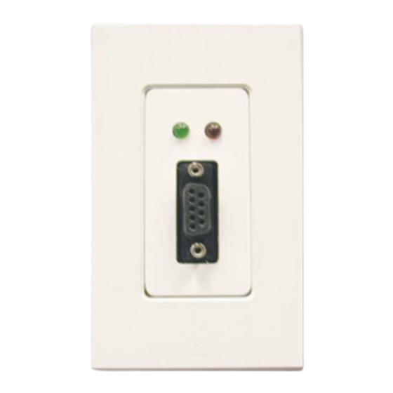
INSTALLATION
The Vision.Net Network consists of a single CAT5e cable connecting all modules in a daisy chain manner. All
units connect to the network using a 9-pin plug-in connector (included).
To install the RS232 serial port interface:
Step 1.
Unpack unit and inspect for any signs of shipping damage. Ensure that two mounting screws are
included.
Step 2.
Connect Vision.Net Network Cable to 9-pin connector at back of RS232 Interface.
PIN
SIGNAL
NO.
1
DATA +
2
DATA –
3
No Connection
4
+NET V
5
Ground
6
+ NET V
7
Ground
8
+ NET V
9
Ground
Step 3.
Insert RS232 Interface into standard deep rough-in box
(not included). Secure with two supplied mounting
screws.
Step 4.
Snap faceplate into place.
NOTE: A standard IBM-compatible computer can be connected to
the Vision.Net Network using the RS232 Interface. The port accepts
a standard one-to-one 9-pin serial cable up to 25 feet (7.5 meters)
in length.
OPERATION
The RS232 Serial Interface Port operates in one of two modes: Vision.net (binary) or Show Control (ASCII).
VISION.NET MODE
1-Stop Bit
19200 Baud
Protocol: Binary
The unit will sense the incoming protocol and automatically switch to the proper mode.
Note: It may take several messages from either the third-party system or the Vision.net Designer PC before the
RS232 Interface switches modes.
63025
Vision.Net RS232 Serial Interface
WIRE COLOR
White / Orange
Orange
N/A
White / Green
Green
White / Blue
Blue
White / Brown
Brown
SHOW CONTROL MODE
8-Bit
©2019 Signify Holding. All rights reserved.
8 Bit
1 Stop Bit
9600 Baud
Protocol: ASCII
W W W. S T R A N D L I G H T I N G .C O M
1
QUICK START GUIDE
Vision.Net Cable
Vision.Net RS232
Faceplate
Advertisement
Table of Contents

Subscribe to Our Youtube Channel
Related Manuals for Strand VISION.NET RS232 Series

Summary of Contents for Strand VISION.NET RS232 Series
- Page 1 QUICK START GUIDE VISION.NET RS232 SERIAL INTERFACE This document provides basic setup instructions and safety warnings for the following product(s): 63025 Vision.Net RS232 Serial Interface INSTALLATION The Vision.Net Network consists of a single CAT5e cable connecting all modules in a daisy chain manner. All units connect to the network using a 9-pin plug-in connector (included).
- Page 2 VISION.NET RS232 SERIAL INTERFACE QUICK START GUIDE COMMUNICATIONS These are the communication protocols available for use with the RS232 Serial Port Interface. • Vision.Net Protocol (binary) • ASCII TABLE 1. ASCII CODES DESIGNER COMMANDS ASCII RS232 NOTES Print Command Help Page HH<cr>...
- Page 3 Strand off ers a two-year limited warranty on its control products against defects in materials or workmanship from the date of delivery. A copy of Strand two-year limited warranty containing specifi c terms and conditions can be obtained from the Strand website at or by contacting your local Strand offi ce.
Need help?
Do you have a question about the VISION.NET RS232 Series and is the answer not in the manual?
Questions and answers