
Related Manuals for SGM LEKTRA VLW602

Summary of Contents for SGM LEKTRA VLW602
- Page 1 VLW602 Display and confi guration unit technical documentation EN Rev. Of 19/07/2022...
-
Page 2: Table Of Contents
VLW602 contents CONTENTS 1-WARRANTY page 3 2-PRODUCT page 4 3-PERFORMANCE SPECIFICATIONS page 5 4-DIMENSIONS page 6 5-ELECTRICAL CONNECTIONS page 7 6-CONFIGURATION AND CALIBRATION page 9 7-QUICK SETUP page 10 8-ADVANCED SETUP page 16 9-FACTORY TEST AND QUALITY CERTIFICATE page 32 Page 2 of 32 www.sgm-lektra.com... -
Page 3: 1-Warranty
Contract. In no circumstances shall SGM LEKTRA be liable for direct, indirect or consequential or other loss or damage whether caused by negligence on the part of the company or its employees or otherwise howsoever arising out of defective goods Page 3 of 32 www.sgm-lektra.eu... -
Page 4: 2-Product
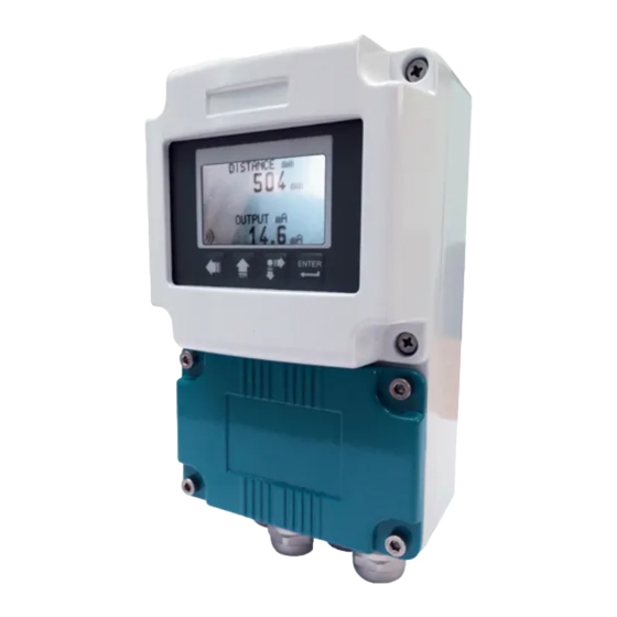
VLW602 - product PRODUCT 1. DISPLAY 2. CONFIGURATION KEYS 3. REMOVABLE CLAMPING PANEL 4. FOUR PG9 CABLE GLANDS IDENTIFICATION Each meter has an adhesive identifi cation plate on which are the meter main data. The following picture describes the information and data on the identifi cation plate. -
Page 5: 3-Performance Specifications
VLW602 - features 3-FEATURES Housing material Epoxy coated aluminum Mechanical installation Wall mountig Protection degree IP66 Keyboard 4 push buttons Display Electrical connection Internal connector Working temperature -25° ÷ +70°C Power supply 12÷30 Vdc 85÷265 Vdc Power consumption Max. 5W... -
Page 6: 4-Dimensions
VLW602 dimensions 4-DIMENSIONS MECHANICAL DIMENSIONS Page 6 of 32 www.sgm-lektra.com... -
Page 7: 5-Electrical Connections
5-ELECTRICAL CONNECTIONS 5.1 CONNECTIONS 1) Separate the engine control cables or power cables from the VLW602 connection cables. 2) Remove the caps from the cable glands and open the cover by unscrewing the screws. 3) Lead the cables into the transmitter through the cable glands. - Page 8 VLW602 electrical connections 5.3 Connection L(+) N(-) Page 8 of 32 www.sgm-lektra.com...
-
Page 9: 6-Configuration And Calibration
VLW602 - confi guration and calibration 6-CONFIGURATION AND CALIBRATION Via the VLW602 the operator can: access any transmitter function, change confi guration parameter settings and other functions. 6.1 VLW602 FEATURES The VLW602 program module has 4 buttons which allow to perform all operational, control and programming instrument functions. -
Page 10: 7-Quick Setup
VLW602 - quick setup 7-QUICK SETUP 7.1 - Quick Setup menu structure Parameter Default Values 1500mm (PTU50 1.5mt max) Set Distance 4mA 6000mm (PTU51 6mt max) 0000 mm 12000mm (PTU56 12mt max) 100mm (PTU50 1.5mt max) Set Distance 20mA 400mm (PTU51 6mt max) - Page 11 VLW602 - quick setup 7.2.1 SET DISTANCE 4mA DISTANCE 4mA DISTANCE 20mA MEDIUM Press ENTER to display the distance value associated with 4mA output. FILTER COEFFICENT BLIND DISTANCE DISPLAY Use SCROLL and UP ARROW to modify that value; in the example the 4mA SET DISTANCE 4mA distance is 3500mm.
- Page 12 VLW602 - quick setup 7.2.3 MEDIUM DISTANCE 4mA DISTANCE 20mA MEDIUM Press ENTER to display the previous setting. FILTER COEFFICENT BLIND DISTANCE DISPLAY Press SCROLL to select the medium type. Press ENTER to confi rm. LIQUIDS SOLIDS LIQUIDS PIPE LIQUIDS...
- Page 13 VLW602 - quick setup 7.2.4 FILTER COEFFICIENT DISTANCE 4mA DISTANCE 20mA MEDIUM Press ENTER. FILTER COEFFICENT Use SCROLL and UP ARROW to modify the value. Input a value from 1 to 99. BLIND DISTANCE 1 maximum speed, 99 maximum slowness.
- Page 14 VLW602 - quick setup 7.2.5 BLIND DISTANCE DISTANCE 4mA DISTANCE 20mA MEDIUM Press ENTER. The BLIND ZONE is used to avoid undesired measures near to the FILTER COEFFICENT transmitter. BLIND DISTANCE DISPLAY Use SCROLL and UP ARROW to modify the value. Press ENTER to confi rm.
- Page 15 VLW602 - quick setup 7.3 - ECHO MAP Pressing LEFT ARROW, from RUN mode, to access directly to the echoes digital map display, which are in PTU50-51-56 receiving. This function is useful for: properly orient the transducer pointing. verify the echoes in acquisition correctness.
-
Page 16: 8-Advanced Setup
VLW602 - advanced confi guration 8-ADVANCED CONFIGURATION 8.1 - “SETUP” MENU SET DISTANCE 4mA 0000mm SETUP SET DISTANCE 4mA SET DISTANCE 20mA 0000mm SET DISTANCE 20mA LIQUIDS MEDIUM SOLIDS LIQUIDS PIPE FILTER COEFFICIENT FILTER COEFFICIENT BLIND DISTANCE BLIND DISTANCE ACTUAL LEV 4mA... - Page 17 VLW602 - advanced confi guration 8.2.1 - SET DISTANCE 4mA SET DISTANCE 4mA SET DISTANCE 20mA MEDIUM Position the cursor on DISTANCE 4mA, press ENTER to access. FILTER COEFFICIENT BLIND DISTANCE ACTUAL LEV 4mA ACTUAL LEV 20mA Use UP ARROW and SCROLL to modify the value.
- Page 18 VLW602 - advanced confi guration 8.2.5 - BLIND DISTANCE SET DISTANCE 4mA SET DISTANCE 20mA MEDIUM Position the cursor on DISTANCE 4mA, press ENTER to access. FILTER COEFFICIENT Represent the “BLIND ZONE” BLIND DISTANCE ACTUAL LEV 4mA ACTUAL LEV 20mA Input the desired value in order to avoid measures near the surface of the sensor (if necessary).
- Page 19 VLW602 - advanced confi guration 8.3 “DISPLAY” menu DISTANCE mm >1 VALUE DISPLAY DISPLAY VALUES LEVEL mm 2 VALUES LEVEL % OUTPUT mA 1 VALUE TEMPERATURE °C >2 VALUES >PRIMARY VALUE DISTANCE mm SECONDARY VALUE LIVEL mm LCD CONTRAST LCD CONTRAST...
- Page 20 VLW602 - advanced confi guration 8.4.1.2 - 2 VALUE Position the cursor on 2 VALUE, press ENTER to access. 1 VALUE 2 VALUES Two values are displayed; itʼs possible to choose which one is the primary and which is the secondary, each with a choice of 5 parameters.
- Page 21 VLW602 - advanced confi guration 8.4.2 - LCD CONTRAST DISPLAY VALUES LCD CONTRAST Position the cursor on LCD CONTRAST, press ENTER to access. WELCOME TEXT itʼs possible to adjust the contrast of LCD, simply increasing or decreasing the value of a parameter from 0 to 63.
- Page 22 VLW602 - advanced confi guration 8.5 “DIAGNOSTIC” menu TEMPERATURE NO ECHO FOUND DISABLE DIAGNOSTIC MAX GAIN ALARM CONFIGURATION >ENABLE ECHO IN BLIND DISTANCE >120% MEASURE STATUS MEASURE STATUS G : 00000 FROZEN GAIN FROZEN GAIN MAX GAIN TH MAX GAIN TH.
- Page 23 VLW602 - advanced confi guration 8.6.2 - MEASURE STATUS ALARM CONFIGURATION MEASURE STATUS FROZEN GAIN Position the cursor on MEASURE STATUS, press ENTER to access. MAX GAIN TH. PEAK VALUES OUTPUT SIMUL. Itʼs possible to display the gain of the system, with values from 0 to 255.
- Page 24 VLW602 - advanced confi guration 8.6.5.1 - DISPLAY VALUES Position the cursor on DISPLAY VALUES, press ENTER to access. DISPLAY VALUES RESET VALUES Displays the max. and min. distance measured from power on. LEFT ARROW to exit. PEAK VALUES NB - The peak values stored are erased every time the PTU50-51-56 turns-off...
- Page 25 VLW602 - advanced confi guration 8.7 “SERVICE” menu 21.5 mA SERVICE OUTPUT SAFE MODE 3.85 mA HOLD LAST VALUE PROBE UID SET PROBE UID SET UNIT UID SET UNIT UID SET UID SEARCH OK TO BEGIN ENGLISH LANGUAGE ITALIANO FRANCAIS...
- Page 26 Place the cursor on SET UNIT UID and press ENTER to enter. UID SEARCH In this parameter it is possible to assign the UID address of VLW602 for MODBUS RTU communication with the PTU probe having the same UID address.
- Page 27 VLW602 - advanced confi guration 8.8.3 - LANGUAGE OUTPUT SAFE MODE Position the cursor on LANGUAGE, press ENTER to access. LANGUAGE FREQUENCY Sets the menu language: English, Italian, French F_WINDOW RESTORE SETTING PASSWORD LOCK Press SCROLL to select the menu language.
- Page 28 Position the cursor on ENABLE LOCK and press ENTER to enter. In this parameter it is possible to disable or enable the password protection to block access to the programming menus of the VLW602. DISABLE Use the UP ARROW and SCROLL to select the setting.
- Page 29 VLW602 - advanced confi guration 8.9 - PROBE INFO SETUP DISPLAY Position the cursor on INFO, press ENTER to access. DIAGNOSTIC SERVICE In addition to information about the manufacturer, are displayed the PROBE INFO fi rmware revision and the confi guration index UNIT INFO 8.10 - UNIT INFO...
- Page 30 VLW602 - note _______________________________________________________________________________________ _______________________________________________________________________________________ _______________________________________________________________________________________ _______________________________________________________________________________________ _______________________________________________________________________________________ _______________________________________________________________________________________ _______________________________________________________________________________________ _______________________________________________________________________________________ _______________________________________________________________________________________ _______________________________________________________________________________________ _______________________________________________________________________________________ _______________________________________________________________________________________ _______________________________________________________________________________________ _______________________________________________________________________________________ _______________________________________________________________________________________ _______________________________________________________________________________________ _______________________________________________________________________________________ _______________________________________________________________________________________ _______________________________________________________________________________________ _______________________________________________________________________________________ _______________________________________________________________________________________ _______________________________________________________________________________________ _______________________________________________________________________________________ _______________________________________________________________________________________ _______________________________________________________________________________________ _______________________________________________________________________________________ _______________________________________________________________________________________ _______________________________________________________________________________________ _______________________________________________________________________________________ _______________________________________________________________________________________ _______________________________________________________________________________________ _______________________________________________________________________________________ _______________________________________________________________________________________ _______________________________________________________________________________________ _______________________________________________________________________________________ _______________________________________________________________________________________ _______________________________________________________________________________________...
- Page 31 Page 31 of 32 www.sgm-lektra.eu...
-
Page 32: 9-Factory Test And Quality Certificate
Documentation subject to technical change with no prior warning 9-FACTORY TEST AND QUALITY CERTIFICATE In conformity to the company and check procedures I certify that the equipment: (Display and confi guration unit) is conform to the technical requirements on Technical Data and it is made in conformity to the procedure Quality Control Manager: ............
Need help?
Do you have a question about the VLW602 and is the answer not in the manual?
Questions and answers