Table of Contents
Advertisement
Quick Links
Advertisement
Table of Contents

Subscribe to Our Youtube Channel
Related Manuals for ASTECH VLM500-MID


Summary of Contents for ASTECH VLM500-MID
- Page 1 User Manual VLM500-MID Version 1.0...
- Page 2 Registered trademarks are the manufacturer’s property. VLM500-MID – User Manual V1.0 Copyright © ASTECH Angewandte Sensortechnik GmbH, Rostock 2020 VLM500-Series as of hardware version 2018, Firmware version as of V1.31r0 CDB-Series as of hardware version 2018, Firmware version as of V1.24r1 Date of printing: 10.10.2020...
-
Page 3: Table Of Contents
Contents VLM500-MID User Manual Table of contents Table of contents ............................3 Commands and parameters of the VLM500-MID ..................5 List of figures ............................7 List of tables ............................. 8 General information ..........................9 Information on how to work with this manual ...................... 9 Safety instructions ............................... - Page 4 VLM500-MID User Manual Contents Process data output (not legally relevant, optional) .................... 43 8.9.1 Profinet IO..............................43 8.9.2 EtherNet/IP ............................... 46 8.9.3 Ethernet ..............................46 Maintenance ............................47 General ................................47 VLM500 - Window ............................. 47 LED lamp ................................48 Service application VLMTool ........................
-
Page 5: Commands And Parameters Of The Vlm500-Mid
Contents VLM500-MID User Manual The command Expmax ......... 56 Commands and The command Expmin .......... 56 parameters of the The command Direction ........56 VLM500-MID The command Holdtime ........57 VLM500 The command Illumination ........57 System commands The command Illmax..........57 The command Illmin .......... - Page 6 VLM500-MID User Manual Contents The command AOValue ........69 Non-legally relevant commands The command PO1Factor ........69 The Command %additionalunit ......76 The command PO1Hold ........70 The Command %article1 ........76 The command PO1On .......... 70 The Command %article2 ........77 The command PO1Output ........
-
Page 7: List Of Figures
Contents VLM500-MID User Manual List of figures Figure 1: The VLM500-MID as a part of a length measuring machine ............... 10 Figure 2: Simplified structure of a VLM500 ...................... 12 Figure 3: Checksums ............................14 Figure 4: Software identification ........................14 Figure 5: CDB with programming adapter ...................... -
Page 8: List Of Tables
VLM500-MID User Manual Contents List of tables Table 1: Indicators of the VLM500-MID ......................13 Table 2: VLM500 device models ........................17 Table 3: Display symbols and there meaning ....................18 Table 4: Data output structure ........................40 Table 5: Profinet Process data modes ......................44 Table 6: EtherNet/IP data structure ......................... -
Page 9: General Information
Do not stare at operating lamp. It may be harmful to the eye. Machine directive 2006/42/EC In the sense of the EU directive “2006/42/EC” the VLM500-MID is not a machine. Hence there is no conformity declaration available for the device. The directive 2006/42/EC regularizes the requirements on machines. Here, a machine is meant to be the entity of connected parts or mechanisms (see also EN 292-1, section 3.1). -
Page 10: Device Description
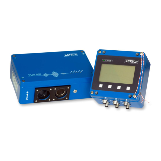
General The VLM500-MID consists of the two main components VLM500 and CDB. The VLM500 is the sensor. The CDB is a display and storage unit. The length values recorded by the VLM500 are displayed on the CDB screen. When a length measurement has been completed, the length value is saved together with status information as a data record in the CDB. -
Page 11: Measuring Principle
In the case of a manual length measurement, the measured value must be confirmed by pressing a key so that it can be saved automatically. If the VLM500-MID is equipped with a data interface, this data record is automatically output to the data interface (not legally relevant). Furthermore, metadata (e.g. batch number, article number) can be transmitted to the CDB for protocol purposes. -
Page 12: Figure 2: Simplified Structure Of A Vlm500
VLM500-MID User Manual Device description white light LED is used to illuminate the measurement object. Due to the broadband nature of the light, the greatest possible degree of surface independence is achieved. Any extraneous light that occurs is effectively suppressed by using a differential measurement method. -
Page 13: Led-Indicators
Device description VLM500-MID User Manual 2.4 LED-Indicators The VLM500-MID has integrated LED to display operating states. The VLM500 has five LED in the lid, whereas the CDB has one LED in the membrane keyboard. Table 1: Indicators of the VLM500-MID... -
Page 14: Software Integrity And Software Identification
The software automatically carries out the integrity check every 60 minutes. If at least one of the checksum deviates from the reference value, the user is informed of this state with a message and the VLM500-MID is switched to the unsecured state. -
Page 15: Preset Length Outputs
VLM500-MID User Manual 2.6 Preset length outputs The VLM500-MID has two switching outputs for adjustable preset length. These switch when the currently measured length value is equal to or greater than a previously programmed target length. These nominal lengths (preset length) can be set via the user interface of the CDB. Both values are entered in meters. For more information how to adjust the values via the user interface refer chapter 5.7. -
Page 16: Operating Modes
That means intentional or unintentional parameter or other changes shall be impossible. Precautions have been taken for the VLM500-MID that meet these and other requirements. When a length measurement machine is calibrated, the VLM500-MID is in secure mode. The secure mode is represented by attaching seals and lead seals to both the VLM500 housing and the CDB housing (see the photo on the cover sheet of this user manual as an example). -
Page 17: Device Models
Device models VLM500-MID User Manual Device models Different device models of the VLM500 series are available, which are electrically- and connection-compatible. Most options (interface cards, assembly accessories etc.) can be used for all models. The differences in measurement range, working distance and distance variance result from the used optics and the signal processing of the devices VLM500A, VLM500D and VLM500L. -
Page 18: Cdb Handling
The CDB is supplied with power via the VLM500. The CDB is therefore switched on together with the VLM500. After switching on, the ASTECH logo is shown on the CDB display. This is followed by the display test, the integrity check of the software and the display of the software identification. -
Page 19: Menu Structure
CDB Handling VLM500-MID User Manual If this occurs, the device can still be operated and used. However, new measured values are saved as invalid measured values. The software identification (version numbers of the software) is displayed after the checksums. After this automatic switch-on test run, the menu measurement display is automatically displayed. A length measurement process can then be started right away. -
Page 20: Figure 9: Cdb Menu Structure
VLM500-MID User Manual CDB Handling Figure 9: CDB menu structure page 20 ASTECH GmbH... -
Page 21: Measurement Display
(in m/s) • display of the length in a second (alternative) unit (can be set by the user) • working mode of the VLM500-MID • amount of available and occupied memory • date and time •... -
Page 22: Stored Data
5.5.2 Storage period and memory size The storage capacity in the VLM500-MID offers space for a total of 3,938,104 data records. If a memory location is occupied, the next free memory location is used automatically. If all storage locations are occupied and the minimum period for storing the oldest data record has not been exceeded, no more datasets can be saved. -
Page 23: Searching For Specific Measurement Data
CDB Handling VLM500-MID User Manual If user likes to have a printout of the dataset, the corresponding printer button needs to be pressed one time. To share the data set with a PLC, PC, Server, the - button must be pressed on time. The meta data (e.g. article number/name, machine name) of a dataset can be showed by pressing the - button. -
Page 24: Invalid Measured Values
If a saved dataset was defined as invalid by the software, it is copied in the list of invalid measured values. There can be three reasons for an invalid dataset. First, the VLM500-MID was in unsecured mode while the dataset was saved. -
Page 25: Figure 15: Cdb Status Page
In- and outputs Shows the logic condition of all CDB in- and outputs. This information can be used to check the voltage levels of external connected signals. Error list Shows all current pending error of the VLM500-MID system ASTECH GmbH page 25... -
Page 26: Settings
The behavior of the CDB can be adjusted by using the settings menu. The following table lists the available options. Working mode The working mode sets the way a measurement is done with the VLM500-MID. The available options are: manual sequence triggered sequence. - Page 27 German English. Test mode Activating the Test mode turns the VLM500-MID into To test parameter changed while the VLM500-MID is a special operation mode. It used to change any in secured mode, the Test mode can be used for that.
-
Page 28: Performing A Measurement Process
"triggered sequence" should be selected in the VLM500-MID. For other cases where cutting to length is done by hand, the "manual sequence" should be selected. The working mode is set via the menu item "Settings / Working mode"... -
Page 29: Figure 18: Timing Diagram Of An Edge-Triggered Length Measurement
Performing a measurement process VLM500-MID User Manual Edge triggered (see Figure 18): With each edge change (H/L or L/H) of the trigger signal, a new length measurement begins and ends. The current length value is displayed continuously. Figure 18: Timing diagram of an edge-triggered length measurement In any case, in trigger mode, when a trigger event occurs, the length value with additional information is automatically stored as a data record in the memory. -
Page 30: Assembly
VLM500-MID User Manual Assembly Assembly 7.1 VLM500 The assembly is done transversally to the direction of movement of the measuring object (see drawing in the annex chapter 14.6). The standard direction of movement (forward) is determined as from housing bottom to housing lid. -
Page 31: Figure 21: Vlm500 With Linear Unit Lj2
Assembly VLM500-MID User Manual The assembly is made rectangular from the material’s direction of movement with a maximum tolerance of ±1°. If the alignment is not made with the stated tolerance, measuring errors may occur. Optional linear units also allow an adjustment in case of changing material distances (LJ1 for one axis) or for round surfaces as e.g. -
Page 32: Cdb
VLM500-MID User Manual Assembly 7.2 CDB The housing of the CDB has four holes in the bottom of the housing through which the CDB can be attached. The cover does not have to be removed because the holes are also present in the cover. The drilling pattern can be looked up in section 14.6. -
Page 33: Connections And Interfaces
The device connections 1, 4 and 5 on the VLM500 are optional and are only equipped with a flange if an additional output interface (pulses, analog, process data) has been purchased with the VLM500-MID Device connections that are not connected are to be protected against the ingress of dirt by means of blind plugs. -
Page 34: Power Supply And Grounding
8.2 Power supply and grounding The VLM500-MID operates with a 24 V DC power supply (20 to 30 V). The supply takes place via device connection 3 on the VLM500. The CDB is power supplied from the VLM500 via the VLM500/CDB connection cable. -
Page 35: Service Interface Usb
Windows must be fully started for the driver to be installed. The "IUSB_driver_FTDI.zip" file must be extracted to a known location on a hard drive. Then the VLM500-MID is connected to the PC. It is advisable to first connect the end of the cable to the CDB and then the other end of the cable to the PC. Windows should now have recognized the new hardware and search for a driver. -
Page 36: Printer Connection
VLM500-MID User Manual Connections and Interfaces Note: The VLM500-MID does not have to be switched on to install the driver. The FT230X is supplied with power by the PC and thus enables the driver to be installed. If the VLMTool is installed, the user is automatically offered to install the USB driver as well. For this it is recommended not to connect the VLM to the PC. - Page 37 Connections and Interfaces VLM500-MID User Manual XON/XOFF flow control. With SO4INTERFACE the communication baud rate can be selected. For USB, RS-232 or RS-422/485 the value is free. For Profinet IO, EtherNet/IP or Ethernet the baud rate is fixed to 57600.
-
Page 38: Serial Interface
VLM500-MID User Manual Connections and Interfaces Suppress label print out If the CDB parameter %PRINTDOC is set to “A” (auto), a label is automatically printed for each completed measurement. In certain situations, this printout is not wanted, e.g. test measurements, adjustment or set-up processes. -
Page 39: Profinet Io
M12, 4-pin, D-coded, Binder series 715. A GSDML file is provided and can be installed on the PLC side. The IFPN provides a webserver with a webpage (IP address of VLM500-MID, port 80) with information about the device and the last transmitted data set. See Figure 28. -
Page 40: Table 4: Data Output Structure
VLM500-MID User Manual Connections and Interfaces Configuration The IFPN is configured using the Profinet IO controller. Interface-specific parameters such as the IP address to be used, the subnet mask, the gateway, the name or the mode can be changed. Data output The data output from the CDB (slave) to a Profinet master takes place synchronously with the storage of a data record in the CDB and has the structure shown in Table 4. -
Page 41: Ethernet/Ip
CDB over long distances using standardized network components. The IFEI provides a webserver with a webpage (IP address of VLM500-MID, port 80) with information about the device and the last transmitted data set. See Figure 28. An EDS file is provided and can be installed on the PLC side. -
Page 42: Analog Output (Not Legally Relevant, Optional)
VLM500-MID User Manual Connections and Interfaces 8.7 Analog output (not legally relevant, optional) The IAUN interface card provides an optically isolated analog output (current interface) with a 16-bit resolution. There are three versions with different current ranges available: IA00 (0-20 mA), IA40 (4-20 mA) and IA04 (0- 24 mA). -
Page 43: Push Pull 24V (Ippp)
Connections and Interfaces VLM500-MID User Manual The card can drive RS-422 inputs with a 100 Ohm terminating resistor. The connection is symmetrical between OUTx and / OUTx. The GND-connection is not used. When using twisted-pair and shielded cables (e.g. CAT5), the maximum cable length for the RS-422 is 500 m. -
Page 44: Figure 30: Vlm500 Profinet Sensor Page
(see Table 5) can be changed. The device description file (GSDML) for the Profinet IO controller is available for download on the ASTECH website and is part of the scope of delivery. The following two notes must be observed when exchanging data: The parameterization of the VLM500 must correspond to the mode used, which is set by the user in the Profinet IO controller. - Page 45 Connections and Interfaces VLM500-MID User Manual 17 ms 16 Bit counter, 32 Bit speed, 16 Bit measurement rate 32 Bit Integral of speed, 32 Bit 1 ms Timer <not in use> 15 ms 16 Bit counter, Z L:H...
-
Page 46: Ethernet/Ip
DHCP. If no DHCP server is available, the IP address 192.168.0.51 applies to the VLM. The device description file (EDS) for the EtherNet/IP scanner is available for download on the ASTECH website. The speed output via Ethernet/IP is always unsigned! Data structure All values are transferred as an amount! The sign of the speed and length is coded in the device status. -
Page 47: Maintenance
Maintenance 9.1 General The VLM500-MID works optically. It is dependent on seeing the measurement object. Thus, it is necessary to check the VLM500 window in regular intervals and clean it, if necessary. The cleaning should be made with a soft, lint-free cloth and customary glass cleaner. -
Page 48: Led Lamp
Secured mode If the VLM500-MID is in the secured operating mode, the housing of the VLM500 is sealed. A change of the light source is only possible if the seal is removed. Changing the light source has no effect on the measuring behavior of the VLM500-MID. -
Page 49: Service Application Vlmtool
To end the communication channel, you can press the right button of the CDB key pad, close the VLMTool or press the “Back to CDB” button shown over the VLM picture of the VLMTool. In any case the VLM500-MID restarts and after the boot process length measurements can then be made again. -
Page 50: Commands And Parameters Of The Vlm500
In order to carry out test measurements (e.g. speed diagram, behavior of the measuring rate etc.) with the VLM500-MID, the menu item "Test mode" must be called up via the user interface. Refer chapter 5.7. This is a special mode that can only be used with the VLM500 itself. No length measurement values can be saved in the CDB. -
Page 51: Commands For System Information
Commands and parameters of the VLM500 VLM500-MID User Manual 11.5 Commands for system information Command Description Syntax This command shows all parameters of the analog output. Constant The command returns the system constant. This constant contains several Constant calculation factors for the velocity that results from different lenses and magnification factors. -
Page 52: Legally Relevant Parameters
VLM500-MID User Manual Commands and parameters of the VLM500 Command Description Syntax Temperature Two temperatures are displayed in °C unit from inside the device. As soon Temperature as 75 °C is exceeded the Error 'E31 Over temperature detected!' is activated. - Page 53 Commands and parameters of the VLM500 VLM500-MID User Manual The command Average The command is used for setting the averaging time for the velocity and measuring rates calculation. The internal calculation of the length is independent from the set averaging time! In the time set by Average, all accruing signals (bursts) are compressed to an average value.
- Page 54 VLM500-MID User Manual Commands and parameters of the VLM500 ������������ ���������� ������������������������ = ������������������������ ∙ ������������������ ���������� When the calibration factor is entered as negative value, the sign of the speed and length values is inverted. The meaning of the parameter Direction remains unaffected.
- Page 55 Commands and parameters of the VLM500 VLM500-MID User Manual Syntax: Controltime [f] (f = 0.01 ... 1.00) Unit: The command Controlhold The command allows the freezing of the control loops for adjustment to the brightness of the material surface dependent on the trigger state (see page 63, The command Trigger). There are different application fields:...
- Page 56 VLM500-MID User Manual Commands and parameters of the VLM500 With bright materials with structure, a locking of Exposure to a small value can also be useful in order to prevent a constant readjustment of the exposure time. The command Expmax This command sets the maximum value of the exposure time of the CCD line (see page 55, The command Exposure) that can be accepted by its automatic control.
- Page 57 Commands and parameters of the VLM500 VLM500-MID User Manual If the direction is controlled via a field bus, it is mandatory to set the parameter Direction to 2 or The command Holdtime If a signal failure occurs during a measuring process, a duration can be specified with this command in which the last recorded velocity value is kept on the corresponding interface.
- Page 58 VLM500-MID User Manual Commands and parameters of the VLM500 The parameter should be left to the setting 0. Failures are possible by overloading in incorrect setting of the parameter. The command Lengthoffset With this command it is possible to add an offset value to the optical noncontact measured length. In this manner the distance of two light barriers can be programmed directly.
- Page 59 Commands and parameters of the VLM500 VLM500-MID User Manual The command OED This command controls the function of the quick overexposure detection. Syntax: OED [n] (n = 0 – off, 1 – on) The fast overloading detection should only be switched on, if bright measuring objects enter in the measuring window (e.g.
- Page 60 VLM500-MID User Manual Commands and parameters of the VLM500 The command Senslevel This command sets the sensitivity threshold of the periodic time analyzer. This can be required if the measurement object shows a weak surface structure. Syntax: Senslevel [n] (n = 0 ... 3)
- Page 61 Commands and parameters of the VLM500 VLM500-MID User Manual Adds the value a (V, L, F, ...) with the offset x Multiplies the value a (V, L, F, ...) with x a:H[:n] Returns the value a (V, L, F, ...) as hexadecimal number with n characters a:n[:m] Returns the value a (V, L, F, ...) as formatted number with n places and m decimal places...
-
Page 62: Table 8: Parameter For Command Tracking
VLM500-MID User Manual Commands and parameters of the VLM500 The command SO1On The data output on the serial interface is switched on or off with this command. Data output is interrupted during the command input and processing! Syntax: SO1On [n]... - Page 63 Commands and parameters of the VLM500 VLM500-MID User Manual Meaning Typical use tracks the velocity at zero, additional search Continuous processes for structurally poor, non- function for bad signals metallic surfaces with or without start from zero (Measuring object runs with velocity greater than zero one or accelerates slowly from zero;...
-
Page 64: Figure 33: Active Length Measurement Or Active Trigger Signal Depending On The Command Trigger
VLM500-MID User Manual Commands and parameters of the VLM500 It is measured continuously. A trigger edge stops the measuring and triggers the next measuring simultaneously. Figure 33: Active length measurement or active trigger signal depending on the command Trigger The concerned output channel is updated simultaneously with a stop of the length measurement by trigger synchronous (see commands AOSync, PO1Sync, PO2Sync, PO3Sync, SO1Sync and SO2Sync). -
Page 65: Legally Relevant Commands
Commands and parameters of the VLM500 VLM500-MID User Manual The command Window The parameter Window was implemented for highly dynamic velocity measurements in production process and for feedback control problems. This calculates the weighed moving average according to signal quality over the frequency of the individual burst. - Page 66 VLM500-MID User Manual Commands and parameters of the VLM500 Command Description Syntax Restart A restart of the device is triggered with this command. The parameter is Restart thereby reset with the Store command to the last saved values. Restore This command loads the specified parameter set from the stated storage place Restore [n] [s] to the main memory of the VLM.
- Page 67 Commands and parameters of the VLM500 VLM500-MID User Manual Command Description Syntax Update The command changes a parameter in the boot loader without specification. Update [n] An update of the Firmware of the device can take place in the boot loader. The boot loader indicates the required steps.
-
Page 68: Non-Legally Relevant Parameter
VLM500-MID User Manual Commands and parameters of the VLM500 11.8 Non-legally relevant parameter The parameters that are not legally relevant are parameters that do not affect the recording of measured values. 11.8.1 Analog output An analog current value can be output with an analog output (optional extension card IAUN). A digital/analog converter is used. -
Page 69: Commands For Pulse Output 1
Commands and parameters of the VLM500 VLM500-MID User Manual The command AOMax The maximum value for analog outputs is determined with this command. Syntax: AOMax [f] (n = -1000.0 ... 1000.0) Depending on the parameter DIRECTION it may be necessary to adjust the value for AOMAX for a negative value, if the device is assembled backwards to the direction of movement. - Page 70 VLM500-MID User Manual Commands and parameters of the VLM500 The minimum possible output frequency for the pulse output is 0.2 Hz. If the output value is lower, no pulses are output! The maximum possible output frequency depends on the installed interface boards and their output wiring.
-
Page 71: Commands For Pulse Output 2 And 3
Commands and parameters of the VLM500 VLM500-MID User Manual If option PO1Value Q is set, the measuring rate (like at PO1Value R) is output during the measurement and in case of signal failure or standstill of the measuring object the product (Quality) out of light brightness and exposure time (Exposure) at the pulse output. -
Page 72: Non-Legally Relevant Commands
Leave By calling this command, the communication channel to the VLM500 Leave that was previously set up (CDB command %COMVLM) is eliminated. The entire VLM500-MID is restarted. Savenlp The command only saves the non-legally relevant parameters Savenlp permanently in the device. The non-legally relevant parameters are inserted into the parameter set last selected by the Store or Restore command. - Page 73 Commands and parameters of the VLM500 VLM500-MID User Manual Command Description Syntax during the test commands! The test stops after 60 s or by pressing ESC. Option: c – The test doesn’t stop after 60 s. TestFilter A row of parameters and values is displayed that have effects on the TestFilter [c] filter board or give information about their function.
- Page 74 VLM500-MID User Manual Commands and parameters of the VLM500 Command Description Syntax output is interrupted during the test commands. The test stops after 60 s or by pressing ESC. Option: c – The test doesn’t stop after 60 s. TestComp...
-
Page 75: Commands And Parameters Of The Cdb
Commands and parameters of the CDB VLM500-MID User Manual 12 Commands and parameters of the CDB All commands that have a direct effect on the CDB begin with a percent sign "%". If a parameter of the CDB is changed (regardless of whether it is legally relevant or non-legally relevant), it is automatically stored permanently. -
Page 76: Non-Legally Relevant Commands And Parameter
VLM500-MID User Manual Commands and parameters of the CDB If the automatic changeover between summer and winter time is activated, a check is made when the time is changed to determine whether the time entered falls within summer or winter time. - Page 77 If the VLM500-MID is switched off, the 'ERROR' output is always passive (open). The Command %info When this command is called, information is output via the VLM500-MID. After switching on the VLM500-MID, the information is automatically output to the service interface.
- Page 78 VLM500-MID User Manual Commands and parameters of the CDB The Command %machine The command is used to set the character string “Machine”. This character string is printed on the label and is stored in the data set. The string can be a maximum of 20 characters long. Umlauts and spaces are not permitted.
- Page 79 Commands and parameters of the CDB VLM500-MID User Manual The Command %restart The command restarts the VLM500-MID. A running length measurement is aborted by a restart. Syntax: %restart The Command %readdata The command enables the stored measured values to be read out via the programming interface. The datasets are not changed when reading out.
- Page 80 VLM500-MID User Manual Commands and parameters of the CDB The following values are possible for the baud rate: n: 9600; 19200; 38400; 57600; 115200 Description Protocol type No protocol Software protocol (XON / XOFF-Codes) Parity No parity Odd parity Even parity...
-
Page 81: Technical Data
Technical data VLM500-MID User Manual 13 Technical data VLM500 VLM500A VLM500D VLM500L VLM500E Nominal distance and working range 185 ± 15 mm 240 ± 15 mm 185 ± 10 mm 330 ± 30 mm - extended working range 185 ± 15 mm 240 ±... -
Page 82: Appendix
VLM500-MID User Manual Appendix 14 Appendix 14.1 Parameter overview VLM500 Legally relevant parameter Table 9: Legally relevant VLM500 parameter Command Explanation unit range Presetting Amax Acceleration range 0… 10 Amplifier Signal amplification 0 ... 3 - fix a - Automatic... - Page 83 Appendix VLM500-MID User Manual Command Explanation unit range Presetting Minrate Monitoring measurement rate 0 - off, 1 ... 99 – on Mode Switching grating constant 0 - single, 1 - double Fast overexposure recognition 0 - off 1 - on...
-
Page 84: Table 10: Non-Legally Relevant Vlm500 Parameter
VLM500-MID User Manual Appendix Non-legally relevant parameter Table 10: Non-legally relevant VLM500 parameter Command Description unit range Presetting AOMin Minimum value -1000.0 ... 1000.0 0.000 AOMax Maximum value -1000.0 ... 1000.0 1.000 AOOn Analog output activation 0 - off 1 - on... -
Page 85: Parameter Overview Cdb
Appendix VLM500-MID User Manual 14.2 Parameter overview CDB Legally relevant parameter Table 11: Legally relevant CDB parameter Command Description unit range Presetting %date Setting of date of CDB Central European Summer Time (CEST) %duration Setting of time period, a data... -
Page 86: Error Numbers
VLM500-MID User Manual Appendix 14.3 Error numbers All error messages begin with the letter ‘E’ and a two-digit error number. The last five errors that occurred are cached during the operation from error code ‘E10’ on. The command Error shows the numbers and error texts. - Page 87 Appendix VLM500-MID User Manual Code Description Cause of error E24 No direction board found The entered command is not Setting DIR to auto is not allowed accepted because an automatic without an automatic direction direction detection is not installed detection board (DIRB)
- Page 88 VLM500-MID User Manual Appendix Code Description Cause of error E47 – E49 Not in use E50 Analog 12V out of range The voltage 12V is out of range 24V voltage supply is instable Internal hardware error E51 Analog 5V out of range...
-
Page 89: Table 14: Error Codes Of Cdb
Appendix VLM500-MID User Manual Table 14: Error codes of CDB Code Description Cause of error E00 No ERROR No error occurred E01 Missing parameter No or too few parameters Incorrect command input specified E02 Value out of range Number too small or too big... -
Page 90: Terminal Assignment
Device connection CDB 3 The device connection 3 is intended for the parameterization of the VLM500-MID. Physically, it is a USB interface that is installed on the PC as a virtual COM port. The following table shows the pin assignment of connection 3. -
Page 91: Table 18: Device Connection 4, Cdb
Appendix VLM500-MID User Manual Device connection CDB 4 The device connection 4 is intended for the connection of switching inputs and outputs. The following table shows the pin assignment of connection 4. Connection type: 8 pole, plug female, A coding. -
Page 92: Plug Connector
VLM500-MID User Manual Appendix 14.5 Plug connector Assembly instructions for plug connector M12 Figure 35: Assembly instruction for shielded plug connectors connections 1, 2, 4 and 5 This connector can be connected to ports 1, 4 and 5 on the VLM500 and to ports 2, 3, 4 and 5 on the CDB. -
Page 93: Figure 37: Assignment Of The Plug Connector (Display On The Plug Page)
Appendix VLM500-MID User Manual Contact assignment cable plugs and cable boxes Cable plug 5 pole, M12, A coding Cable plug 5 pole, M12, A coding Different inputs and outputs, e.g. analog output RS-232 Cable plug 8 pole, M12, A coding... -
Page 94: Dimensional And Installation Drawings
VLM500-MID User manual Appendix 14.6 Dimensional and installation drawings All dimensions in mm. Figure 38: Dimensional and installation drawings for VLM500 Device WD [mm] X [mm] A-Series D-Series L-Series E-Geräts The working distance (WD) is always measured starting at the objective window. -
Page 95: Figure 39: Dimensional And Installation Drawings For Cdb
Appendix VLM500-MID user manual Figure 39: Dimensional and installation drawings for CDB ASTECH GmbH Seite 95... -
Page 96: Declaration Of Conformity
VLM500-MID User manual Declaration of conformity 15 Declaration of conformity Manufacturer ASTECH Angewandte Sensortechnik GmbH Address 18057 Rostock Schonenfahrerstr. 5 Germany Product name VLM500 Description Optical length and velocity measuring device This product (seen as a counter) was checked by the German Physikalisch Technische Bundesanstalt PTB with respect to the WELMEC-guide 8.8.
Need help?
Do you have a question about the VLM500-MID and is the answer not in the manual?
Questions and answers