Table of Contents

Summary of Contents for Exhausto MB-GATEWAY
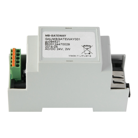
- Page 1 3005392-2015-10-28 • Network Module gateway Technical manual EXHAUSTO A/S Odensevej 76 DK-5550 Langeskov Art.-no. GAUMBGATEWAY001 Tel. +45 65 66 12 34 P0101_BO_0001 Fax +45 65 66 11 10 exhausto@exhausto.dk www.exhausto.dk...
-
Page 2: Table Of Contents
TABLE OF 1 INTRODUCTION........................3 CONTENTS 2 INSTALLATION MANUAL ....................3 2.1 Connection ........................3 2.2 Installation ........................4 2.3 Configuring ........................4 2.4 Restoring factory defaults ..................4 2.5 Updating of the firmware using MicroSD card ........... 4 2.6 FTP server ......................... 5 3 MODULE WEB INTERFACE .................... -
Page 3: Table Of 1 Introduction
INTRODUCTION Network Module MB-GATEWAY is used to connect EXHAUSTO air handling units to the computer network (Ethernet). Module functions: • TCP/IP Modbus gateway • IPV4 protocol • WEB server • FTP server • Building of Modbus commands using HTTP requests •... -
Page 4: Installation
If you are going to use some MB-GATEWAYs in the same LAN, you need to change their IP addresses. LAN cannot have more than one unit using the same IP address, thus for configuring of the MB-GATEWAY you need to connect it directly to the PC. -
Page 5: Ftp Server
When the update is finished, the file FIRMWARE.BIN is automatically deleted. Indications of the RJ45 connector LEDs: • Both LED indicators flashes slowly and synchronously – MB-GATEWAY has no firmware installed. • LED indicators flashes slowly in an alternating way – the firmware is being updated. -
Page 6: Module Web Interface
MODULE WEB INTERFACE Number Function Displays the MAC address of the MB-GATEWAY module Number Function Click to switch to the English language Click to switch to the Lithuanian language Click to switch to the Russian language Click to switch to the French language... - Page 7 Function The IP address of the MB-GATEWAY module is set The baud rate of MB-GATEWAY module RS485 communication line is set The parity of MB-GATEWAY module RS485 communication line is set The date and time of MB-GATEWAY module is set...
-
Page 8: Web Control Of The Air Handling Unit With Prv Automatics
WEB CONTROL OF THE AIR HANDLING UNIT WITH PRV AUTOMATICS 4.1. Main window Number Function Displays the remaining time of the BOOST function in minutes It is displayed when the BOOST function is active. Displays the date and time Displays the outdoor air temperature Displays the extract (room) air temperature Displays the supply air temperature Displays the extract air humidity... -
Page 9: Temperature Setting Window
Click to turn on/off the ventilation Click to turn on/off the "BOOST” function (now it is active) Click to turn on/off the "Stand-by" mode Click to open the Alarms list window. It is displayed when there is at least one active fault message Click to open the temperature setting window Click to open the fan speed setting window... -
Page 10: Fan Speed Setting Window
4.3 Fan speed setting window Number Function Click to return to the main window Click to activate the "Stand-by" mode Click to turn on the fan speed 1 Click to turn on the fan speed 2 Click to turn on the fan speed 3 Click to turn on/off the "BOOST"... -
Page 11: Fault List Window
4.4 Alarm list window Number Function Displays the message about active protection (see the table in pg. 11) Number Function Click to return to the main window Click to clear alarms and to restart the system Meaning Plate heat exchanger frost protection function Fire alarm Dirty filter alarm Fans overheat alarm... -
Page 12: Menu Window
4.5 Menu window Number Function Click to return to the main window Click to open the settings window Click to open the status monitoring window Click to open the weekly schedule setting window Click to switch to the green theme Click to switch to the blue theme Click to switch to the black theme... -
Page 13: Settings Window. Set The "Boost" Function Time
Click to open the night-time cooling function settings window Click to open the date and time settings window Click to open the filter timer settings window Click to open the MB-GATEWAY module settings window which is shown when it is connected for the first time... -
Page 14: Settings Window. Set The Desired Co2 Level
4.7 Settings window. Set the desired CO2 level The selection is active when the CO2 sensor is used. Number Function Displays the desired CO2 level setting (PPM) Number Function Click to return to the settings window Click to increase/decrease the CO2 level setting... -
Page 15: Settings Window. Night-Time Cooling Function Settings
4.8 Settings window. Night-time cooling function settings Number Function Displays the maximum allowable outdoor air temperature setting Displays the room air temperature setting Displays the minimum allowable outdoor air temperature setting Displays the air change interval setting in hours Number Function Click to return to the settings window Click to turn on/off the night-time cooling function (now it is turned on) B3 B4 Click to increase/decrease the maximum outdoor air temperature setting... -
Page 16: Date And Time Settings Window
4.9 Date and time settings window Number Function Displays the day Displays the month Displays the year Displays hours Displays minutes Number Function Click to return to the settings window Click to synchronize the time with the PC clock B3 B8 Click to increase/decrease the day setting B4 B9 Click to increase/decrease the month setting Click to increase/decrease the year setting... -
Page 17: Filter Timer Settings Window
4.10 Filter timer settings window Number Function Displays the remaining filter time in hours Displays the set filter timer limit in hours Displays working time in hours Number Function Click to return to the settings window Click to reset the filter timer... -
Page 18: State Monitoring Window
4.11 State monitoring window This window is for monitoring of system status. Amount of the information changes dy- namically depending on the configuration. Number Function Exhaust air temperature Supply air temperature Outdoor air temperature Extract (room) air temperature Percentage of the extract air fan speed Percentage of the supply air fan speed Fan speed setting The state of the fan power circuit (turned on/off ) -
Page 19: Weekly Schedule Setting Window
Numeris Funkcija Click to return to the menu window 4.12 Weekly schedule setting window Number Function Displays the event number. 8 total events per day Displays the selected weekday Displays the hour of event beginning Displays the minute of event beginning Displays the set event fan speed Displays the set event temperature Displays details of deleted event Number... -
Page 20: Weekly Schedule Setting Window. Copying Of Day's Events
Click to paste copied details of another event B8 B9 Click to decrease/increase hour value B10 B11 Click to decrease/increase minute value B14 B15 Click to decrease/increase the set fan speed value B16 B17 Click to decrease/increase the set temperature value 4.13 Weekly schedule setting window. -
Page 21: Programmer's Guide
Е.g. „http://address/ F(1106000100039A9B)“. Function returns a full Modbus response. • The main MB-GATEWAY parameters in XML format: „http://address/INFO” • http://address/TON – enabling Modbus transmitter state. • http://address/TON(filename) – enabling Modbus transmiter state providing the request file. Е.g. „http://address/TON(custom.txt)” – activated •... - Page 22 Example of Modbus transmitter request file: 140323870006>0110214F; 01031FFF0006>14102381; 1403237C0005>011020FF; 0103208F0005>14102377; Explanation of file content: • “140323870006>0110214F;”: o “14” – read from a device that has an address of 20 (0x14); o “03” – Modbus command (Read Holding Registers); o “2387” – starting with address 9095 (0x2387); o “0006”...
Need help?
Do you have a question about the MB-GATEWAY and is the answer not in the manual?
Questions and answers