Advertisement
Quick Links
Installation, Operation &
Maintenance
Instructions
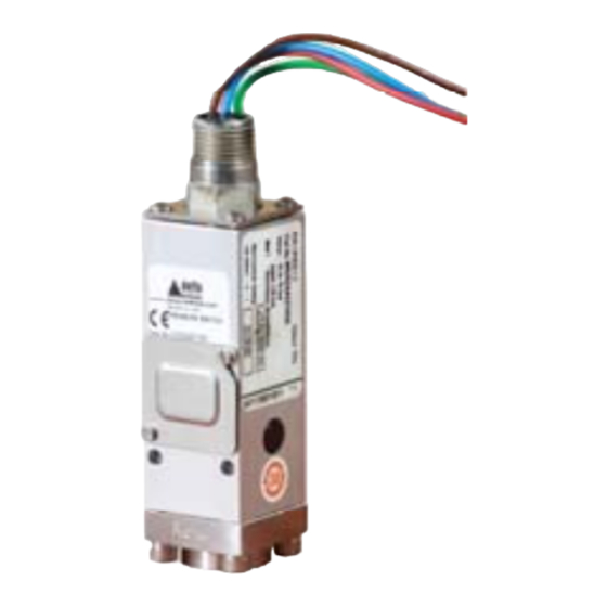
GR Series
Models GR2, GR4 (Pressure Switches)
Models GR3, GR6 (Differential Pressure Switches)
Model GR7 (Temperature Switches)
General
The unit is manufactured, checked and supplied in
accordance with our published specification, and
when installed and used in normal or prescribed
applications, with the lid in place and within the
parameters set for mechanical and electrical
performance, will not cause danger or hazard to life
or limb.
THE USERS ATTENTION IS DRAWN TO
THE FACT THAT, WHEN THE UNIT IS
'LIVE' WITH RESPECT TO ELECTRICAL
OR PRESSURE SUPPLIES, A HAZARD
MAY EXIST IF THE UNIT IS OPENED OR
DISMANTLED.
UNITS
MUST
INSTALLED BY SUITABLY TRAINED AND
QUALIFIED
ACCORDANCE
CODES OF PRACTICE SO THAT THE
POSSIBILITY OF FAILURE RESULTING IN
INJURY
OR
MISUSE
AVOIDED.
THE MICROSWITCH ASSEMBLY WITH
FACTORY SEALED LEADS HAS BEEN
CAREFULLY
FACTORY.
RENDER THIS UNIT INOPERATIVE.
Operating principles
Pressure Switch models GR2, GR4 and Differential
Pressure Switch models GR3, GR6 are diaphragm
operated switches.
These diaphragms generate a force proportional to
the applied pressure and are balanced by a user
adjustable control spring. When the force exceeds
that created by the control spring, the diaphragm
moves causing a push rod to actuate a snap-acting
micros-witch.
Temperature model GR7 works in the same way as
the Pressure models with the exception that the
applied pressure comes from the expansion of a
vapour enclosed in either a rigid stem or semi-rigid
thermal system.
BE
SELECTED
PERSONNEL
WITH
APPROPRIATE
DAMAGE
CAUSED
OR
MISAPPLICATION
POSITIONED
AT
ANY
DISTURBANCE
www.delta-mobrey.com
INSTALLATION
Mounting (All models)
The instruments are designed to be mounted
vertically with the process connection underneath.
However, mounting up to 45° from the vertical in any
plane is acceptable, although a small calibration shift
may occur. They can be mounted either direct to
process, or to a wall or panel using the back plate
provided. Select the mounting point so as to avoid
stresses, excessive shock, vibration or temperature
fluctuation being imparted to the switch during
operation. Instruments should be mounted to avoid
excessive heat transfer from the process lines or
adjacent plant. To avoid undue stresses being
imparted
to
AND
mounted, it is recommended that a short length of
flexible line be installed between the instrument and
IN
process line. If sudden changes of pressure
(pulsations) are likely then we recommend that
snubbers are fitted between the process line and
instrument.
BY
IS
ALWAYS HOLD A WRENCH ON THE
PRESSURE ENTRY HEX WHEN MAKING
PRESSURE
SWITCH. DO NO TIGHTEN BY TURNING
THE
THE ENCLOSURE.
MAY
CHECK THE CONNECTION THREAD SIZE
AND SPECIFICATION ON THE UNIT TO
AVOID
PROCESS CONNECTION ADAPTOR. SEE
DIGIT 11 OF PRODUCT CODE.
Mounting (Model GR7- Rigid Stem)
Assemble the unit via a thermowell, using the
spanner facility provided and ensuring that:
a) the sensing bulb is fully immersed in the
process temperature
b) the sensing bulb does not bottom out in the
thermowell which could cause damage
Mounting (Model GR7 - Capillary system)
Mount the sensing bulb so that the capillary end is
above the bulb and the bulb is level with, or no more
than 250mm below the base of the instrument. The
stem is fitted with a sliding compression gland to
accommodate different thermowells.
IOM-GR-B : SEPT 2019
the
instrument
when
CONNECTION
MIS-MATCHING
wall/panel
TO
THE
WITH
THE
Advertisement

Related Manuals for delta-mobrey GR Series


Summary of Contents for delta-mobrey GR Series
- Page 1 IOM-GR-B : SEPT 2019 Installation, Operation & Maintenance Instructions GR Series Models GR2, GR4 (Pressure Switches) Models GR3, GR6 (Differential Pressure Switches) Model GR7 (Temperature Switches) INSTALLATION General The unit is manufactured, checked and supplied in Mounting (All models) accordance with our published specification, and...
- Page 2 Each conductor is provided with an identity tag. If these become detached refer to the colour code in the wiring diagram (Fig 2). Fig 2 Fig 3 www.delta-mobrey.com...
-
Page 3: Operation
LEAST 5 FULL THREADS ARE ENGAGED to have a set point value between 25% and 75% of BETWEEN THE COVER / LID AND THE span. ENCLOSURE WHEN THE UNIT IS IN OPERATION. NEVER OPERATE THE ATEX UNIT UNLESS THIS CONDITION IS MET. www.delta-mobrey.com... -
Page 4: Maintenance
6) Kwikstik 3507 inseal gasket must be fitted If further maintenance is required, seek advice from between GR series adaptor and enclosure to DELTA MOBREY before attempting repair or re- ensure IP66 ingress protection. placement of parts. - Page 5 IOM-GR-B : SEPT 2019 DIMENSIONS Enclosures Styles Sensors www.delta-mobrey.com...