
Summary of Contents for Budmat FWD2HBM BI 2x4
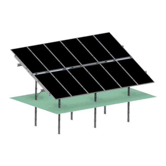
- Page 1 ASSEMBLY AND USAGE INSTRUCTIONS for Photovoltaic Module Support Structure FWD2 HBM BI 2x4 , 2x6...
-
Page 2: Table Of Contents
ASSEMBLY INSTRUCTION Table of Contents GENETAL INFORMATION ....................3 STRUCTURE VARIANTS....................3 SAFETY INFORMATION ....................3 PRODUCT USE ......................4 Maintenance ......................... 4 Cleaning ........................4 PACKAGING, STORAGE AND TRANSPORT ............... 4 ASSEMBLY. GENERAL INFORMATION ............... 5 Tools ..........................5 ASSEMBLY INSTRUCTION ...................... -
Page 3: Genetal Information
ASSEMBLY INSTRUCTION MONTAŻU GENERAL INFORMATION FWD 2 structures are complete systems of free-standing, ground-mounted support structures for photovoltaic panels manufactured in our own machine park. Each PV structure consists of components made of high-quality steel with Magnelis ZM310 and ZM 410 coatings, and it comes with an essential set of screws, nuts, clamps and washers. -
Page 4: Product Use
4. PACKAGING, STORAGE, TRANSPORT The products should be packed in an original BUDMAT package in a manner preventing the loss of any component of the particular system. After receiving the delivery, please always check the product for its quality and possible lack of components in the respective kit(s). -
Page 5: Assembly. General Information
It is prohibited to interfere with the structure by drilling holes, grinding its edges, cutting it or carrying out other activities that may damage its protective layer, unless such an activity is admissible as per the instruction or Budmat consents to such an activity being carried out. -
Page 6: Assembly Instruction
ASSEMBLY INSTRUCTION ASSEMBLY INSTRUCTION 1. COMPONENTS Structure configurations: Modules in vertical alignment in layouts: 2x4, 2x6. Tilt angle: 25˚ 1.1. BASIC STRUCTURE COMPONENT KIT LAYOUT LAYOUT SYMBOL COMPONENT NAME FWD2 HBM BI KD L2200 RAFTER FWD2 HBM BI KG L1824 FWD2 HBM BI MF1 L2200 INVERTER... -
Page 7: Connecting Sets
MID CLAMP SPRING WASHER M10x30 HEXAGON BOLT M12x30 M12 / M10 NUT ENLARGED WASHER RHOMBIC WASHER HEXAGON M8x35 SOCKET SCREW 1.2. CONNECTING SETS: (11) (13) (10) (12) Ł1 – M12 HEXAGON BOLT + M12 ENLARGED WASHER (2 pcs.) + M12 SPRING WASHER + M12 NUT (15) (10) -
Page 8: Assembly
ASSEMBLY INSTRUCTION 2. ASSEMBLY 2.1. POST LAYOUT Post spacing: North <-> South Rys. 1 REAR POST AND FRONT POST CONSIST OF TWO SECTIONS EACH: • FWD2 HBM BI SW L2200 I - DRIVEN INTO THE GROUND: • FWD2 HBM BI SDT L2014 II - CONNECTED: •... -
Page 9: Fig. 2 Post Spacing: East <-> West
ASSEMBLY INSTRUCTION Fig. 2 Post spacing: East <–> West VIEW A – 2x4 Layout, VIEW B – 2x6 Layout POST SPACING BETWEEN TWO ADJOINING TABLES: Distance between tables: For vertical layout, 100mm between purlins are standard. Mark the distances between the post in particular tables before the assembly. Fig. -
Page 10: Post Mounting
ASSEMBLY INSTRUCTION 2.1.1. POST MOUNTING The post are mounted as per wind rose pattern. Fig. 4 WIND ROSE - Post positioning SECTION DRIVEN INTO THE GROUND: FWD2 HBM BI SW L2200 Fig. 5 POST LAYOUTS IN 2x4 AND 2x6 TABLES JOIN THE POSTS WITH A Ł5 CONNECTING SET... -
Page 11: Binder Assembly
ASSEMBLY INSTRUCTION Fig. 6 MANNER AND POINTS OF POST CONNECTION 2.2. BINDER ASSEMBLY Fig. 7 2x4 and 2x6 TABLE LAYOUTS Before assembling the binders, connect the particular binders with a Ł5 connecting set. Join the binders in the manner shown below and connect them with 3 connecting sets. -
Page 12: Fig. 8 Assembly Of Binders In A 2X4 Layout
ASSEMBLY INSTRUCTION Fig. 8 ASSEMBLY OF BINDERS IN A 2x4 LAYOUT Fig. 9 ASSEMBLY OF BINDERS IN A 2x6 LAYOUT CONNECT THE BINDER TO THE POST WITH A Ł1 CONNECTING SET. Fig. 10 Binder connection points in 2x4 and 2x6 layouts... -
Page 13: Rafter Assembly
ASSEMBLY INSTRUCTION Fig. 11 Binder connection 2.3. RAFTER ASSEMBLY Before connecting the rafters to the binders, connect particular rafter components with a Ł5 connecting set. Connect the rafters in the manner shown below with 4 connecting sets. Fig. 12 WIND ROSE - Rafter positioning Fig. -
Page 14: Fig. 14 Distribution Of Rafters In 2X4 And 2X6 Tables
ASSEMBLY INSTRUCTION Fig. 14 Distribution of rafters in 2x4 and 2x6 tables CONNECT EACH RAFTER TO THE REAR AND FRONT BINDER WITH A Ł1 CONNECTING SET. Fig. 15 Rafter connection point... -
Page 15: Brace Assembly
ASSEMBLY INSTRUCTION 2.4. BRACE ASSEMBLY Before connecting the BRACES to the POSTS, connect their particular components with a Ł5 connecting set. Connect the BRACES in the manner shown below with 3 connection sets WHEN CONNECTING THE BRACE TO A 2X4 TABLE, ITS FINAL LENGTH MUST BE L2741. WHEN CONNECTING THE BRACE TO A 2X6 TABLE, ITS FINAL LENGTH MUST BE L3101. -
Page 16: Pv Panel Assembly
ASSEMBLY INSTRUCTION 2.5. PV PANEL ASSEMBLY Assemble your PV panels in accordance with the instruction issued by the manufacturer. ASSEMBLE THE PANELS WITH A Ł2 AND Ł3 CONNECTING SET Fig. 18 PANEL DISTRIBUTION IN 2x4 and 2x6 LAYOUTS Fig. 19 Module assembly... -
Page 17: Inverter Mounting Assembly
2.6. INVERTER MOUNTING ASSEMBLY ASSEMBLE THE INVERTER MOUNTING WITH A Ł5 CONNECTING SET Before connecting the INVERTER MOUNTING to the POSTS, connect their particular components with a Ł5 connecting set. Connect the MOUNTINGS in the manner shown below with 3 connecting sets. The final inverter mounting length must be L2620. -
Page 18: Table Of Figures
TABLE OF FIGURES Fig. 1 Post spacing: North <-> South ....................8 Fig. 2 Post spacing: East <–> West ...................... 9 Fig. 3 Post spacing between tables ..................... 9 Fig. 4 WIND ROSE - Post positioning ..................... 10 Fig. 5 POST LAYOUTS IN 2x4 AND 2x6 TABLES ..................
Need help?
Do you have a question about the FWD2HBM BI 2x4 and is the answer not in the manual?
Questions and answers