
Subscribe to Our Youtube Channel
Summary of Contents for Planer MR7
- Page 1 ® INSTRUCTIONS FOR USE © 2022 Planer Limited Original instructions MA200524-EN 5.0.430...
-
Page 3: Table Of Contents
Sending email using Gmail ........................28 2.3.2 Licensing the application ..................30 2.3.3 Adding users ......................30 2.3.3.1 Access levels ............................31 2.3.3.2 MR7 Controller specific access levels ....................32 2.3.4 Configuring the password constraints ..............32 MR7 : INSTRUCTIONS FOR USE MA200524-EN 5.0.430... - Page 4 Returning the freezer to ambient ................55 Viewing Kryofiles ......................56 5.9.1 To view a stored Kryofile ..................56 5.9.2 Printing a Kryofile ....................56 5.9.2.1 Printer ............................... 57 5.9.2.2 PDF (File) ..............................57 5.9.2.3 PDF (Email) .............................. 57 MR7 : INSTRUCTIONS FOR USE MA200524-EN 5.0.430...
- Page 5 Changing the line colours .................... 61 Advanced configuration ....................61 Changing your password ..................... 65 6.5.1 Resetting a password ..................... 65 Controlling the MR7 using a PC .................. 66 File locations ......................... 68 Mirrored Kryofiles ......................69 Equipment list Routine maintenance and troubleshooting MR7 service schedule ....................
- Page 6 Table of contents 9.1.4 Chamber specifications ..................85 9.1.5 Fuses ........................86 9.1.5.1 Series 300 ..............................86 9.1.5.2 Series 500 ..............................86 9.1.6 Batteries ......................... 86 External alarm connection ..................86 Index MR7 : INSTRUCTIONS FOR USE MA200524-EN 5.0.430...
-
Page 7: Introduction
Introduction... -
Page 8: Notices
This manual only applies to the following models: MR7 Series 300 and 500 This guide has been designed to help you install and use the MR7. The guide includes important information regarding safe use of the equipment and it is important that you familiarise yourself with this document before attempting to install or operate the equipment. -
Page 9: Intended Use Statement
Refer to these instructions. Failure to follow these instructions may result in personal or third-party injury. Manufacturer Consult instructions for use. Swiss Representative European Representative Medical Device Model number Product name No tools Direct current (DC) input. Primary PT100 input. MR7 : INSTRUCTIONS FOR USE MA200524-EN 5.0.430... - Page 10 Introduction Secondary PT100 input. Serial port connection. Ethernet connection. USB connections. SD card. Controlled-rate freezer connector. Alarm output connector. Do not dispose of with general waste. MR7 : INSTRUCTIONS FOR USE MA200524-EN 5.0.430...
-
Page 11: Symbols Used In The Application
Move selection from right-hand list to left-hand list Move selection from left-hand list to right-hand list Move selection upwards in a list Move selection downwards in a list Add an item to a list Remove an item from a list MR7 : INSTRUCTIONS FOR USE MA200524-EN 5.0.430... -
Page 12: Welcome
Access the ports menu Ports Access the profiles menu Profiles Access the manual override menu Cool/Heat View Kryofiles Kryofiles Access the Users page Access the Settings page Settings Shut down the application Shut dow n MR7 : INSTRUCTIONS FOR USE MA200524-EN 5.0.430... -
Page 13: Alarm Symbols
Create a new profile View a profile View Edit a profile Edit Delete a profile Delete Run a profile View the profile steps Steps Edit the profile steps Steps View profile steps as a graph Chart MR7 : INSTRUCTIONS FOR USE MA200524-EN 5.0.430... -
Page 14: Manual Override Symbols
Symbols used to show information about the profile are also available when viewing a Kryofile; see Profile symbols 1.5.10 User symbols Add a new user View users View Edit your own details Edit Edit a user Edit MR7 : INSTRUCTIONS FOR USE MA200524-EN 5.0.430... -
Page 15: Settings Symbols
If the skin is blistered or there is any possibility that eyes have been affected, the patient should be taken immediately to a doctor or hospital for treatment. 1.6.2 Safety 1.6.2.1 Equipment 1.6.2.1.1 Warnings WARNING MR7 : INSTRUCTIONS FOR USE MA200524-EN 5.0.430... -
Page 16: 1.6.2.1.2 Precautions
EN60950 or its equivalent. Use with other equipment may compromise the safety of the device. The unit should only be connected to an Ethernet local area network (LAN) internal to the building. MR7 : INSTRUCTIONS FOR USE MA200524-EN 5.0.430... -
Page 17: Liquid Nitrogen And Vessels
1.6.3 EMC precautions CAUTION The following precautions must be taken to ensure that the equipment is not damaged by electrostatic discharge (ESD), and that its immunity to radio frequency interference is not compromised. MR7 : INSTRUCTIONS FOR USE MA200524-EN 5.0.430... -
Page 18: About The Mr7
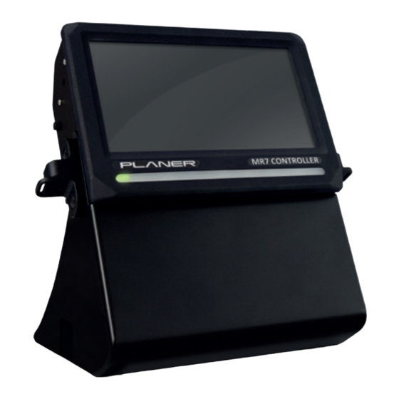
Take care to avoid placing the equipment in environments influenced by sources of electromagnetic interference, such as large transformers. About the MR7 The key parts of the complete system are shown below. Fig.1 Key parts of the MR7 system 1. Touchscreen 2. Power and alarm indication strip 3. Monitor stand 1.7.1... - Page 19 Introduction 1. MR7 Controller: the user interface and temperature controller. This comprises two internal subsystems: a. IO Control Board: measures the current temperature and adjusts the amount of liquid nitrogen or heat that is supplied to the chamber. b. Host Board: provides the user interface and downloads profiles to the IO Control Board to be executed.
-
Page 20: Connection Overview
Introduction 1.7.2 Connection overview 1.7.2.1 MR7 Controller All connectors are at the bottom of the MR7 control box. Fig.2 Connections on the MR7 control box DC power input Controller rate freezer connector. Primary temperature probe input Secondary temperature probe input Serial port. -
Page 21: Chamber
All connectors are located at the back of the freezer. Fig.3 Connections on the back of the 300 series freezer Liquid nitrogen inlet INPUT SAMPLE Sample temperature probe input LNP4 Power outlet for LNP4 pump only ONLY MAINS Mains power inlet INLET MR7 : INSTRUCTIONS FOR USE MA200524-EN 5.0.430... - Page 22 Introduction Fig.4 Connections on the back of the 500 series freezer Liquid nitrogen inlet REMOTE Sample temperature probe input Power outlets for MR7 and accessories POWER MAINS Mains power inlet INLET MR7 : INSTRUCTIONS FOR USE MA200524-EN 5.0.430...
- Page 23 Getting started...
-
Page 24: Getting Started Installing The Equipment
5. Connect the network connection from the MR7 Controller to the local area network, unless you are using the WIFI dongle. 6. For 370 and 570 systems, connect the 15 way chamber connection to the freezer connector on the MR7 Controller. -
Page 25: Installing The Liquid Nitrogen Supply
Installing the liquid nitrogen supply WARNING Installation must only be undertaken by suitably trained personnel. Your service provider will connect the chamber to a liquid nitrogen cylinder or a Planer pump and dewar. Software installation The MR7 Controller comes with the DeltaTv7 application pre-installed. In order to make... -
Page 26: Basic Configuration
The application can be configured to use a port other than 8082 if required; see Configuring email and web access MR7 needs to be able to access an STMP email server and this must be configured to allow emails to be sent by the application. -
Page 27: Configuring Email And Web Access
(ie. needs a password to gain access). mailFrom Your MR7 System will send you email notifications about run status and alarms. Set this to the email address used to identify emails sent by MR7 System (eg Delta Tv7@company name.com). -
Page 28: Sending Email Using Gmail
Getting started 2.3.1.1 Sending email using Gmail Email sent from DeltaTv7/MR7 via a Gmail account requires an application password to be created and the settings below to be set. To create an application password for Gmail : 1) Visit https://myaccount.google.com/ and log in using your Gmail account. - Page 29 MR7_sn45678 Click the Generate button. A new password will be created to be used for DeltaTv7/MR7. Record this for entry later as it is not possible to recover the password once Done is pressed. Tap Done. The screen will show a list of the App Passwords on the...
-
Page 30: Licensing The Application
<Your gmail address> 6) Click Done. 2.3.2 Licensing the application When running on the MR7 Controller, the application is already licensed and no action is required. 2.3.3 Adding users 1. From the main menu, Click Users 2. Click New 3. -
Page 31: Access Levels
A fourth access level, Planer Support, is also available but this login is only available to Planer support engineers. The access level of None is used to define users who may want to receive emails but otherwise cannot access the system. -
Page 32: Mr7 Controller Specific Access Levels
Freezer configuration Manual heat or cool Manual calibration Network configuration WiFi configuration 2.3.4 Configuring the password constraints 1. To change the password constraints, click settings 2. Click Edit 3. Modify the options shown below. MR7 : INSTRUCTIONS FOR USE MA200524-EN 5.0.430... -
Page 33: Adding The Port
2.3.5 Adding the port The port is the internal communication link in the MR7 Controller. The port is factory configured and does not normally need to be changed. The port will only need to be added if internal components are replaced as part of a service. -
Page 34: System Alarm Types
The application has not been licensed. 2.3.6.1.1 Control deviation alarms The rules for control deviation alarms generated by MR7 are defined below. Control deviation alarms are not generated while going to start. Control deviation alarms are not generated during the first two minutes after starting the actual profile. -
Page 35: Creating A Warming Profile
Once a run has completed and the samples have been removed, the freezer should be returned to room temperature. To do this you should simply run a warming profile. MR7 : INSTRUCTIONS FOR USE MA200524-EN 5.0.430... -
Page 36: Configuring The Control Coefficients
3. The system will automatically read the current settings from the controller. 4. Click Standard to open a list of standard control coefficients. 5. Select the coefficients that match your chamber type and liquid nitrogen supply pressure. The standard options are listed below: MR7 : INSTRUCTIONS FOR USE MA200524-EN 5.0.430... -
Page 37: Configuring The Wired Network
5. Click Done when complete. 2.3.10 Configuring the wireless network The following instructions only apply if your MR7 Controller has been fitted with a wireless adapter. 1. From the main menu, click Settings 2. Click WIFI 3. Consult with your IT department for the correct values to use for the network settings. -
Page 38: Setting Date And Time
HP USB printer installation Introduction The MR7 Host board SW includes HPLIP Linux module related to printing. However, every time a new model HP USB printer is attached to MR7, the corresponding HPLIP driver module needs to be initialised/installed. Note: The instructions are valid for HP printers only. - Page 39 Getting started 3. Connect the USB keyboard to the USB hub. 4. Power on MR7 and wait for the DeltaT start-up screen to appear. 5. Power on the printer and if relevant to the printer used, make sure that both “WiFi Direct”...
-
Page 40: Switching Off The System
Getting started 10. Power down the MR7 using the “Shut down” button. 11. Power up the MR7 and test the use of the printer, when connected via USB cable. Switching off the system CAUTION Switching off the chamber at sub-zero temperatures may cause serious damage to the equipment. -
Page 41: Using A Planer Pump And Dewar
Using a Planer pump and dewar... -
Page 42: Filling A Dewar
Using a Planer pump and dewar Using a Planer pump and dewar This section describes how to use the Planer LNP4 pump and dewar. Filling a dewar WARNING Wear protective clothing. See Liquid nitrogen and vessels Never remove a pump from a dewar until the pressure gauge reading has fallen to zero. - Page 43 3. Press firmly on the top of the pump to hold it level and clip all the springs onto the dewar. Alternate between handles. 4. Close the pressure relief valve. 5. Connect the mains inlet of the pump power supply unit to the auxiliary power output on the rear of the chamber. MR7 : INSTRUCTIONS FOR USE MA200524-EN 5.0.430...
-
Page 44: Testing And Pressurising The Pump
You will need to remove the pump whenever the dewar needs to be refilled. WARNING Wear protective clothing. See Liquid nitrogen and vessels Never remove a pump from a dewar until the pressure gauge reading has fallen to zero. 1. Switch off the equipment. MR7 : INSTRUCTIONS FOR USE MA200524-EN 5.0.430... - Page 45 WARNING Fit a protective cap to the dewar to prevent ice plugs forming. The cap should be in good condition and designed for use with the dewar. MR7 : INSTRUCTIONS FOR USE MA200524-EN 5.0.430...
-
Page 47: Profiles
Profiles... -
Page 48: Profile Terms
This allows time for the samples to reach the seed temperature. The samples are then momentarily removed from the chamber and manually seeded by touching the side of the container with a very cold object, for MR7 : INSTRUCTIONS FOR USE MA200524-EN 5.0.430... -
Page 49: Pulse Seeding
PRF: Profile CHM: Chamber temperature SAM: Sample temperature Ts: Seeding start temperature 1. Profile run until seed start temperature reached. 2. Pulse duration. 3. Chamber automatically returns to profile 4. Remainder of run. MR7 : INSTRUCTIONS FOR USE MA200524-EN 5.0.430... -
Page 50: Automatic Seeding
Profiles Automatic seeding Note Automatic seeding is not currently supported by freezers within the Planer range. With automatic seeding, ice nucleation is initiated by switching on an automatic seeding device when the chamber passes between a start and end temperature. - Page 51 Running profiles...
-
Page 52: Running Profiles Preparing The Nitrogen Supply
Click Next Note After editing a port definition or just after starting MR7, it may take a few minutes for the serial ports to be detected. If you receive a message stating that the freezer is unavailable, click No when asked if you want to continue, wait for a moment, and then try again. -
Page 53: Seeding Samples
Seeding samples 1. If manual seeding has been selected, the controller will prompt you when the samples are ready for seeding. 2. When seeding is complete, press OK to resume the profile. MR7 : INSTRUCTIONS FOR USE MA200524-EN 5.0.430... -
Page 54: Monitoring The Run
At the end of the run, the controller will prompt you when the samples are ready for removal. The controller will hold the chamber at the end temperature until you confirm that all samples have been removed. MR7 : INSTRUCTIONS FOR USE MA200524-EN 5.0.430... -
Page 55: Aborting A Run
Once a run has completed and the samples have been removed, the freezer should be returned to room temperature. To do this you should simply run the warmup profile; see Creating a warming profile MR7 : INSTRUCTIONS FOR USE MA200524-EN 5.0.430... -
Page 56: Viewing Kryofiles
Running profiles Viewing Kryofiles Kryofiles are the reports that are generated when a profile is run. You can either view the stored Kryofiles or retrieve the backup data from the MR7 Controller Note Many actions are initiated by clicking buttons on the toolbar at the bottom of the screen. -
Page 57: Printer
PDF: saves a copy of the report in PDF format. This will be saved in the export file location: see File locations 5.9.2.3 PDF (Email) PDF (Email): emails a copy of the report as a PDF file to the email address of the current user. MR7 : INSTRUCTIONS FOR USE MA200524-EN 5.0.430... -
Page 58: To Retrieve The Backup Kryofile
Advanced configuration . If this setting is false, MR7 will never try to resume a Kryofile in this way, and if any unexpected data are read from the freezer, they will be recorded as an anonymous run to a new Kryofile. -
Page 59: Infrequent Tasks
Infrequent tasks... -
Page 60: Web Browser Access
Infrequent tasks Web browser access MR7 System can be configured to allow remote access to some data using a web browser. If you are remotely accessing your data from outside of your network, it is recommended that you use a VPN. -
Page 61: Viewing The Audit Trail
Take care when modifying these settings. Incorrect values may result in loss of notifications or data. 1. From the main menu, click Settings 2. To change any of the settings, click Edit 3. To reset the settings back to their default values, click Reset MR7 : INSTRUCTIONS FOR USE MA200524-EN 5.0.430... - Page 62 Time over which the mean chamber and sample temperature are calculated. This period is centred on the mid-point of the hold. confirmRunComplete Boolean Set true if the user can acknowledge completion of a run from MR7 System. MR7 : INSTRUCTIONS FOR USE MA200524-EN 5.0.430...
- Page 63 E.g. bold italic. graphXAxisFont Text X axis font name. graphXAxisFontColor Colour X axis font colour. graphXAxisFontSize Integer X axis font size. graphXAxisFontStyle Text X axis font style. graphXAxisTitleFont Text X axis title font name. MR7 : INSTRUCTIONS FOR USE MA200524-EN 5.0.430...
- Page 64 Users' passwords must contain both UpperCase upper and lower case characters. resumeKryofiles Boolean Set true if Kryofiles should be resumed at start-up; see Resuming Kryofiles. startAnnotationRequired Boolean Set true if the user must enter annotations for runs. MR7 : INSTRUCTIONS FOR USE MA200524-EN 5.0.430...
-
Page 65: Changing Your Password
8. You will be informed that a second user will now be required. Click Yes to continue. 9. The second user must now enter his or her authentication details. 10. The password will then be reset and a confirmation message displayed. 11. Click Done when complete. MR7 : INSTRUCTIONS FOR USE MA200524-EN 5.0.430... -
Page 66: Controlling The Mr7 Using A Pc
Infrequent tasks Controlling the MR7 using a PC To run the MR7 from a PC as a satellite you will need to: 1. Connect your MR7 to your PC/Laptop using cable AC200048. 2. Set your MR7 to external control. 3. Configure your port in Delta Tv7 to locate the MR7. - Page 67 Select Edit Click the default port. Select the port that the MR7 is connected to, then click on the arrow symbol move it to the selected window. Click on the freezer symbol to select the device you wish to control.
-
Page 68: File Locations
Delta Tv7 can now be used to control the freezer. File locations Unlike typical desktop applications, MR7 System restricts the locations to which files can be exported. This is to allow the system manager to control the destination for reports. -
Page 69: Mirrored Kryofiles
3. The System Properties Configuration table will be shown. Scroll down the list to find the k ryofileMirrorFolder value and set this to the required location. 4. Click Done when your changes have been made. MR7 : INSTRUCTIONS FOR USE MA200524-EN 5.0.430... -
Page 71: Equipment List
Equipment list... - Page 72 Equipment list Equipment list To service the MR7 the service personnel will require the following equipment: Electronic engineers tool kit. Digital multimeter. Static protection wrist band. Earthing strap. Toolkit: Hex Key: 2.5mm Screwdiver: PZ1, PZ2 Long nose pliers Spanners: 5, 14mm Parts required.
-
Page 73: Routine Maintenance And Troubleshooting
Routine maintenance and troubleshooting... -
Page 74: Mr7 Service Schedule
3. Confirm operation of the MR7 controller by checking a program printout and actual run. 4. Calibrate the MR7 with the freezer that it is to be used with. Note: The MR7 contains automatic adjustment circuitry, which removes the need to adjust the analogue section to account for drifts. -
Page 75: General Cleaning
These instructions are for the exterior of the device only. 1. Clean the monitor periodically with a damp cloth and sterile water or 70% isopropyl alcohol. 2. Allow the unit to dry fully before reconnecting the mains supply. MR7 : INSTRUCTIONS FOR USE MA200524-EN 5.0.430... -
Page 76: Cleaning And Disinfecting The System
6. Wipe the surface over with sterile water and a clean non-lint cloth to remove any residual fluids. Use cotton buds or swabs where necessary to ensure contact is made with all grooves and corners. 7. Leave the unit to dry until all residual cleaning fluids have evaporated. MR7 : INSTRUCTIONS FOR USE MA200524-EN 5.0.430... -
Page 77: Battery Replacement
1. Carefully lift the the display out of the stand. 2. Locate the battery holder. 3. Using a coin, undo the battery-holder cover by rotating anticlockwise. 4. Remove the existing batteries. 5. Fit new batteries ensuring the orientation is correct. MR7 : INSTRUCTIONS FOR USE MA200524-EN 5.0.430... -
Page 78: Calibrating The System
An IEC 751 class A PRT, or equivalent, calibrated at 0 C and connected to a digital multimeter capable of 4 wire resistance measurements to an accuracy of better than +/- 0.03 Ohms at 100 Ohms and a resolution of better than 0.001 Ohms. Calibration probe positions MR7 : INSTRUCTIONS FOR USE MA200524-EN 5.0.430... -
Page 79: Manual Calibration
5. Check the values and then click Send to store the values in the controller's memory. 8.6.2 Emailing a calibration report 1. To receive a printable report by email, select Print/PDF MR7 : INSTRUCTIONS FOR USE MA200524-EN 5.0.430... -
Page 80: Troubleshooting
Should any problem persist, please contact your service provider for assistance. Should a serious incident occur involving the loss of patient samples or injury to the user, you must inform Planer Limited and if within the EU, the competent authority for your country. -
Page 81: Unexpected Reset
If the samples are above their freezing point, allow them to warm up. 8.7.5 The chamber will not cool WARNING Refer to the Safety information first. Check the nitrogen supply. Check the fuses. MR7 : INSTRUCTIONS FOR USE MA200524-EN 5.0.430... -
Page 82: The Chamber Will Not Heat
8.7.8 Returning for service Should the equipment or any part of the equipment need to be sent back to Planer Limited for repair, or if the equipment is to be inspected, maintained or repaired on-site by Planer Limited personnel, a Decontamination Certificate must be completed. This can be downloaded from http://www.planer.com/support/service/decontamination-... -
Page 83: Additional Information
Additional information... -
Page 84: Specifications
(see note). 15 A 230 V~ ±10% 50/60Hz 10 A Note. The equipment is designed to be connected to an Installation Category (over- voltage category) II mains supply as defined in IEC 60364-4-443 MR7 : INSTRUCTIONS FOR USE MA200524-EN 5.0.430... -
Page 85: Controller Specifications
115 V~ ±10% 115 V~ ±10% Power requirements 50/60Hz 50/60Hz 50/60Hz (see note) Includes 10 A 10 A 15 A Controller 230 V~ ±10% 230 V~ ±10% 230 V~ ±10% 50/60Hz 50/60Hz 50/60Hz 10 A MR7 : INSTRUCTIONS FOR USE MA200524-EN 5.0.430... -
Page 86: Fuses
Any circuit connected to the alarm output must meet the requirements for an accessible part as defined in EN 61010-1 or its equivalent. The alarm output must not be used in safety critical applications. External alarm connections should only be made by trained service personnel. MR7 : INSTRUCTIONS FOR USE MA200524-EN 5.0.430... - Page 87 Connector type Phoenix 3 way horizontal PCB header. Manufacturer's part number 1181451 Maximum voltage 30 V DC Maximum current Pin connections in normal operating mode Pin connections in alarm mode or power disconnected MR7 : INSTRUCTIONS FOR USE MA200524-EN 5.0.430...
-
Page 89: Index
DeltaTv6 fire configuration firewall advanced first aid wireless network fitting pump configuring alarms forgotten password email fuses 16, 81, 82, 86 system properties series 300 web browser access series 500 connectors chamber controller MR7 : INSTRUCTIONS FOR USE MA200524-EN 5.0.430... - Page 90 - M - - R - mains 15, 82 maintenance remote access 54, 60 manual seeding remove medical attention sensitive data MR7 : INSTRUCTIONS FOR USE MA200524-EN 5.0.430...
- Page 91 27, 60 size weight battery wireless network SMTP configuring permissions specifications chamber controller series 300 power series 500 power system stages stopped troubleshooting symbols used in the manual used on the equipment system MR7 : INSTRUCTIONS FOR USE MA200524-EN 5.0.430...
- Page 92 Planer Limited, 110 Windmill Rd., Sunbury-on-Thames, Middlesex, TW16 7HD, UK. www.planer.com Tel: +44 (0)1932 755000 MR7 : INSTRUCTIONS FOR USE MA200524-EN 5.0.430...
Need help?
Do you have a question about the MR7 and is the answer not in the manual?
Questions and answers