Table of Contents
Advertisement
Quick Links
Model 5152
Video Generator/Audio Embedder Module
User Guide
Issue 5, September 2013
This User Guide is applicable for
Model 5152 modules with the following order codes:
M5152, M5152-01, M5152-02, M5152-03X, and M5152-04X
with serial numbers 00151 and later
and firmware versions
MCU 2.3 and later (m5152.s19) and FPGA 2.2 and later (m5152.bit)
Copyright © 2013 by Studio Technologies, Inc., all rights reserved
www.studio-tech.com
50185-0913, Issue 5
Advertisement
Table of Contents

Related Manuals for Studio Technologies 5152

Summary of Contents for Studio Technologies 5152
- Page 1 M5152, M5152-01, M5152-02, M5152-03X, and M5152-04X with serial numbers 00151 and later and firmware versions MCU 2.3 and later (m5152.s19) and FPGA 2.2 and later (m5152.bit) Copyright © 2013 by Studio Technologies, Inc., all rights reserved www.studio-tech.com 50185-0913, Issue 5...
- Page 2 This page intentionally left blank.
-
Page 3: Table Of Contents
Installation ..............9 Configuration ..............14 Operation..............22 Technical Notes ............27 Specifications ............... 34 Appendix A—Model 5152 Versions ......35 Appendix B—DC Input/Data and GPI/GPO Interconnection Details ..........36 Appendix C—Model 5152 Front Panel and Printed Circuit Board (PCB) Dimensions...... 38... - Page 4 Model 5152 Video Generator/Audio Embedder Module This page intentionally left blank. Issue 5, September 2013 Model 5152 User Guide Page 4 Studio Technologies, Inc.
-
Page 5: Introduction
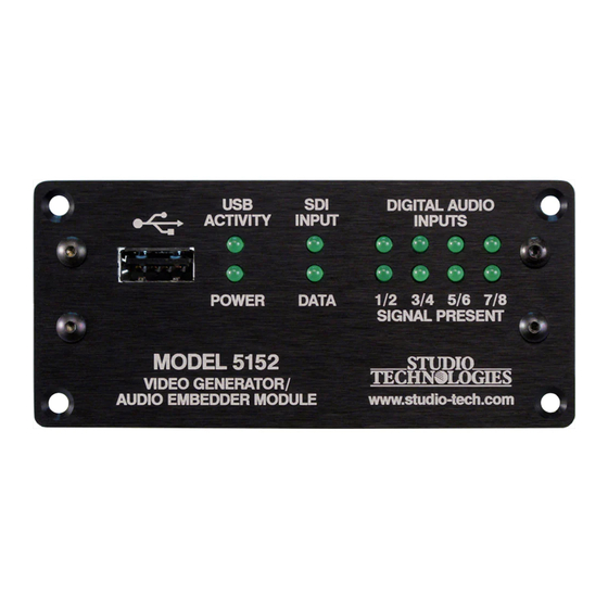
(I/O) locations, and government/ nected to the SDI output whenever an SDI input signal is not present. This ensures Figure 1. Model 5152 Video Generator/Audio Embedder Module front and rear views Model 5152 User Guide Issue 5, September 2013 Studio Technologies, Inc. - Page 6 16 of the 5100-Series equipment. modules to be connected to a Model 5190. For operation the Model 5152 only requires Several Model 5152 operating parameters connection of a few signals. These consist can be configured to meet the needs of of SDI inputs and outputs, up to four unbal- specific applications.
- Page 7 Model 5152 Video Generator/Audio Embedder Module those provided by the Model 5152 will not input the module will generate a high- typically be working with SD-SDI signals. definition (HD- or 3G-SDI) image that will But be assured that many HD-SDI and serve as a “slate,”...
- Page 8 “on air.” the Model 5152. A unique feature of the Model 5152 is its Audio Embedding ability to automatically adapt to the for- The Model 5152 allows four stereo digital mat and rate of a connected SDI signal.
-
Page 9: Installation
ENG-type cameras, are con- Installation nected. Such devices typically embed two or four microphone audio channels into Integration of the Model 5152 into a select- group 1, which need to pass through the ed application should prove quite simple, Model 5152 without interference. - Page 10 (transmitter) modules. patible with SMPTE-compliant HD (1.485 The technical characteristics of the optical Figure 2. Detailed rear view of the Model 5152 Video Generator/Audio Embedder Module showing the MCU and FPGA boards Issue 5, September 2013...
- Page 11 As such, they do not emit suf- output-only SFP module used in the Model ficient power to be considered hazardous. 5152 will have an FP (Fabry-Perot) laser But best safety practices require that the emitting “light” at a wavelength of 1310 optical output port and all unconnected fiber...
- Page 12 9-pin female “D-sub” the Configuration section of this guide (DE-9F) connector located on the back for details. of the Model 5152. Refer to Figure 3 for detailed connection information. Digital Audio Inputs It’s expected that four independent pieces...
- Page 13 RS-485 serial data bus ible with the AMP MTA-100 series of IDC to the Model 5152. Two pins on the mating receptacles. For 22 AWG wire the closed- connector are used to connect a source of end-style receptacle is AMP 3-643813-3;...
-
Page 14: Configuration
100 ohms in series with the GPO will file, STATUS.TXT, is automatically created reduce the current through a typical LED by the Model 5152 and stored on the same to about 5 milliamperes. Note that shorting USB flash drive. - Page 15 SDI signal is detected. SDI Input Select The Model 5152 is capable of having its Moving Image Overlay SDI input in the form of a coaxial signal A “moving”...
- Page 16 This can be important to ensure that a distinction can be made between an active One of the strengths of the Model 5152 is image and an image that’s the result of the its ability to select which of the four digital...
- Page 17 An associated Model 5190 Remote Access PRODUCT= identifies the module’s product Module can be used to directly view firm- type. For the Model 5152 it will be listed as ware (embedded software), hardware, and M5152. This information is provided as a configuration details about a Model 5152...
- Page 18 The range is 0 to 7 seconds. A setting EMBEDON,EMBEDOFF of 0 indicates that there will be no delay. During the delay period the Model 5152 will Figure 8. Example of STATUS.TXT file output a video image with a solid-gray color.
- Page 19 Video Generator/Audio Embedder Module EMBED= identifies how audio signals con- not enabled; the GPO will be low when the nected to the Model 5152 are being em- embedder function is enabled. bedded into the SDI output signal. The first STATUS.TXT File – [OPTIONS] digit represents what happens to the audio associated with digital audio inputs 1 and 2.
- Page 20 2 are being embedded into SDI group name of M5152. When the USB flash drive 1 and digital audio inputs 3 and 4 are being is plugged into a Model 5152 the file will embedded into SDI group 2. automatically be read and the configura- tion stored.
- Page 21 EMBED=NN. This configures the Model The range is 0 to 7 seconds. A setting of 5152 to not embed any audio signals. In 0 selects no delay. During the delay period this situation any embedded audio as-...
-
Page 22: Operation
file but will LED Indicators not be recognized. A brief discussion of the Model 5152’s sta- GPO= selects the status of the GPO (gen- tus LEDs will be covered in this section. - Page 23 LED, it lights whenever the logic device on and off each time data associated with (FPGA) has loaded its firmware and is op- this specific Model 5152 is present. Not all erating normally. This LED is provided only applications will include a connection to for factory troubleshooting use.
- Page 24 1280 x 720 pixel (“720”) or 1920 x 1080 pixel (“1080”) fixed image. During this time period it’s expected that any on-air use of the Model 5152’s output Stored Images can be terminated without alerting viewers that anything is amiss.
- Page 25 This ensures that the Model 5152 “locked” during the transition as the circuit- can generate an SDI signal that matches ry in the Model 5152 was not designed to the requirements of a facility or event. that level of sophistication. This shouldn’t For the module to “learn”...
- Page 26 And, just to clarify, if audio will be embedded into it. a signal is present on the Model 5152’s If a valid signal is present on the selected selected SDI input it will be passed on to...
-
Page 27: Technical Notes
The reason two files are required is simple: eter. When the GPI is shorted to common the Model 5152 does not have the ability to (pulled “low”) the embedding configuration digitally “scale” a 1920 x 1080 image down is temporarily ignored and the embedder to 1280 x 720. - Page 28 6,220,854 bytes, respectively. and “1080” bitmap files that are pre-loaded When created in Adobe Photoshop, the in the Model 5152 at the time of manufac- file sizes should be 2,764,856 bytes and ture. They feature two unique background 6,220,856 bytes, respectively.
- Page 29 1920 x 1080 image must module’s USB port. have a file name of img1080.bmp. Also 7. Power up the Model 5152 module. It ensure that both have the DIB header type will go through its normal power-up BITMAPINFOHEADER so that they can be LED sequence and begin operation.
- Page 30 It will process video and should be noted for later reference. Once audio as well as checking for an FPGA the new files are loaded into a Model 5152 (m5152.bit) file on the USB flash drive. the module’s front-panel LEDs should be If it doesn’t find this file normal opera-...
- Page 31 flash on and off. cally written to a USB flash drive whenever 8. The process of loading the FPGA it is plugged into the Model 5152. This file, (m5152.bit) file will take approximately named STATUS.TXT, provides details of 90 seconds to complete. When the the Model 5152’s firmware (embedded...
- Page 32 SFP Module Flexibility display the major version number with a range of 1-4. The bottom row of four The Model 5152 was designed to allow an LEDs will display the minor version MSA-compliant SFP optical module to be number with a range of 0 (no LED lit) installed at the factory.
- Page 33 It’s possible that special applications could benefit from the features provided by installing these non-optical SFP modules in a Model 5152. For further dialog about this topic please contact Studio Technologies technical support. USB Port Capabilities The USB port, accessible on the Model 5152’s front panel, is provided for use in...
-
Page 34: Specifications
GPI: active low, “pulled up” to 3.3 volts DC using 720p: 50, 59.94, 60 5 k ohm resistor; activates on closure to common 1080i: 50, 59.94, 60 (applies to Model 5152 modules with serial num- 1080p: 23.98, 24, 25, 29.97, 30 bers 00251 and later) 1080psf: 23.98, 24, 25 GPO: active high, 3.3 volts DC with series resis-... -
Page 35: Appendix A-Model 5152 Versions
Model 5152 Video Generator/Audio Embedder Module Appendix A–Model 5152 Versions The following list describes the available Model 5152 versions along with their respective order codes. List is current as of the publication date of this guide. Version Order Code Figure... -
Page 36: Appendix B-Dc Input/Data And Gpi/Gpo Interconnection Details
TE Connectivity (AMP) 3-643813-3, closed-end type Digi-Key part number 3-643813-3-ND Mouser part number 571-3-643813-3 TE Connectivity (AMP) 3-644540-3, feed-through type Digi-Key part number A31121-ND Mouser part number 571-3-644540-3 Issue 5, September 2013 Model 5152 User Guide Page 36 Studio Technologies, Inc. - Page 37 Mouser part number 571-58246-1 Headers on the Model 5152 Printed Circuit Board The actual part number of the header connectors that are soldered into the Model 5152’s printed circuit board is provided in this section. But do not order this part number with the intent of interconnecting signals with the Model 5152! We are providing this detail only so that interested technical personnel can have the full background on the Model 5152’s...
-
Page 38: Appendix C-Model 5152 Front Panel And Printed Circuit Board (Pcb) Dimensions
Model 5152 Video Generator/Audio Embedder Module Appendix C–Model 5152 Front Panel and Printed Circuit Board (PCB) Dimensions Issue 5, September 2013 Model 5152 User Guide Page 38 Studio Technologies, Inc.
Need help?
Do you have a question about the 5152 and is the answer not in the manual?
Questions and answers