Table of Contents
Advertisement
Quick Links
Advertisement
Table of Contents

Summary of Contents for ASC Global InterCom GSM
- Page 1 InterCom GSM GSM DOORPHONE MODULE...
-
Page 2: Table Of Contents
InterCom GSM www.ascglobal.eu Tartalom Device description and function ................................3 Module buildup ......................................4 Figure 4: SIM card insertion ................................4 Installation guide ....................................5 LED signals ......................................6 Connecting the module (PC) ................................. 6 Establishing connection using a Bluetooth adapter ........................... 7 Programming using the PC software .............................. -
Page 3: Device Description And Function
Device description and function The InterCom GSM can be used as an accessory of external units of intercoms until 4 flat systems as well as applicable as a gate control unit too. By using the InterCom GSM, it is not necessary to build a complete intercom system on the grounds that the mobile phones will be used instead of the internal unit. -
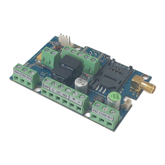
Page 4: Module Buildup
InterCom GSM www.ascglobal.eu Module buildup Figure 4: SIM card insertion... -
Page 5: Installation Guide
InterCom GSM www.ascglobal.eu Installation guide Technical parameters Power voltage: 9-20 VDC Standby power drain: 40 mA + external unit current consumption Maximum power drain: 400 mA + external unit current consumption Relay output load: max. 20V / 500 mA GSM module type: SIMCOM 800... -
Page 6: Led Signals
InterCom GSM www.ascglobal.eu LED signals Signals give essential information of the module, of GSM signal strength and the actual error codes. By blinking we mean flashes between two longer pauses. A STATUS LED (green) gives feedback of signal strength value based on the chart below:... -
Page 7: Establishing Connection Using A Bluetooth Adapter
InterCom GSM www.ascglobal.eu Unknown device In this window search for (which will be the programmer now, later the ✔ Serial port ). If you cannot find it start the “Scan for hardware changes” process from the upper window menu. Device properties can be achieved by double clicking on the unknown device. -
Page 8: Connecting Process
InterCom GSM www.ascglobal.eu Connecting process To program the module choose between USB or Bluetooth connection. Below the language selection in the scroll down list (COM 4 in the picture) you can select the port through which you would like to communicate with the module programmer. You can find this value (in Windows operating system) under Device manager →... -
Page 9: Checking Module Status
InterCom Regardless of the line is broken by the mobile phone, the Intercom GSM does not initiate a call until the talking time has expired. It is advisable to adjust a low vale here to avoid high charges concerning the SIM. -
Page 10: Switching Off Pin Code Request On Sim Card
InterCom GSM www.ascglobal.eu You can reach the actual status through Maintenance → Show module status button By the module status query you will be informed of the followings: input statuses output statuses Tamper sabotage notification power supply failure notification ... -
Page 11: Saving Controlling Phone Numbers
InterCom GSM www.ascglobal.eu Saving controlling phone numbers At the control phone numbers section you can set telephone numbers that can control the outputs. Phone numbers can be stored in the memory of the module (maximum 1,000 pcs). Moreover, additional phone numbers can be stored in the SIM card. -
Page 12: Power Supply Monitoring Setup
InterCom GSM www.ascglobal.eu Tamper connector settings do not differ from any other input settings. On demand connector can be used as a 5th input. If you are using tamper for monitoring case removal input type should be set as closed by default. -
Page 13: Anti Jammer System (Ajs) Settings
The volume of the external unit is adjusted properly (when we switch on the device first time, it is advisable to set the speaker and microphone potentiometer in middle position). If the InterCom GSM provides the power to the external unit, the voltage to the external unit has to be set properly (The voltage can be modified with the potentiometer, next to the outgoing power connector, between 5-15 V). - Page 14 Figure 1: Comelit wiring diagram Figure 2: Biticino wiring diagram Figure 4: Fermax wiring diagram Figure 3: Farfisa md 30 wiring diagram...
- Page 15 InterCom GSM www.ascglobal.eu Figure 6: Kanrich S913 wiring diagram Figure 5: Golmar ER5555 wiring diagram Figure 8: Urmet wiring diagram Figure 7: Siedle wiring diagram...
-
Page 16: Programming With Sms Commands
InterCom GSM www.ascglobal.eu Figure 9: BPT HA 200 wiring diagram Programming with SMS commands Module can also be programmed by SMS commands. SMS starts always with the security code that can be modified whenever you want. Commands can be piled but the SMS length must be under 160 characters. - Page 17 InterCom GSM www.ascglobal.eu saving/editing telephone telephone number (with 1234TEL011=+363055 number x xx: main phone +36) 51234 number of the for notification flat Y: reserved phone number input ordinal 1234INPUT1=INC0010 input setup INPUT number = tnneeeeeeee 0000 t:0 → switched off, 1→24 h...
- Page 18 InterCom GSM www.ascglobal.eu etc.) Setting up notification 1234SEND2=00100000111 sending SEND x 1:1 input = ssssssssvvvvvvvv 10000 ssssssss→ selecting 2.: 2 input phone numbers for SMS 3.: 3 input notification 4.: 4 input (0 or 1) vvvvvvvv→selecting 9.: tamper phone 10.: power...
-
Page 19: Sms Command Examples
InterCom GSM www.ascglobal.eu a limited time (in seconds) Controlling output 3 1234OUT4=00003 Output 3 switches on for 3 seconds Life sign sending LIFETEST cccsstttttttt 1234LIFETEST=007110010 ccc→cycle time, how 01007 often to send message -in 7 days (ex: 030 days) -at 11 a.m.
Need help?
Do you have a question about the InterCom GSM and is the answer not in the manual?
Questions and answers