Table of Contents
Advertisement
Quick Links
INSTALLATION, OPERATING
AND MAINTENANCE MANUAL
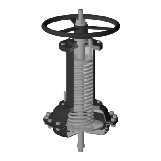
Double Acting
COLUMNLESS PNEUMATIC ACTUATORS
FOR DIAPHRAGM VALVES AF SERIES
1. GENERAL INFORMATION ON THE MANUAL............2
2. NOTES ON POSSIBLE DANGERS .............................2
2.1 Significance of symbols ..............................................2
2.2 Explanatory notes on safety information .....................2
TRANSPORT ......................................................................2
4. DESCRIPTION ..............................................................2
4.1 General Description / Operating principles .................2
4.2 Principle of Operation .................................................3
4.3 Area of Application ......................................................3
4.4 Technical data - remarks ............................................3
4.5 Marking/labelling .........................................................4
5. INSTALLATION ............................................................4
5.1 General remarks on installation ..................................4
5.2 Assembly of the actuator onto de valve: .....................4
5.3 Assembling additional modules ..................................4
5.4 Requirements at the place of installation ....................4
Single Acting
Spring closes
Diaval® AF Series
Contents
6. COMMISSIONING & OPERATION ...............................5
7. CARE AND MAINTENANCE ........................................5
8. TROUBLESHOOTING ..................................................7
9. TROUBLESHOOTING TABLE .....................................7
10. DISMANTLING THE ACTUATOR ..............................8
11. GOODS RETURN & DISPOSAL ...............................8
12. WARRANTY / GUARANTEE......................................8
13. PARTS LIST ...............................................................9
14. ANNEXES .................................................................10
14.1 Declaration of Conformity - DC09 ...........................10
14.2 Data Sheet - DS09 ..................................................10
Single Acting
Spring opens
Page 1
Advertisement
Table of Contents

Summary of Contents for Comeval Diaval AF Series
-
Page 1: Table Of Contents
INSTALLATION, OPERATING AND MAINTENANCE MANUAL Single Acting Spring closes Double Acting Single Acting Spring opens Diaval® AF Series COLUMNLESS PNEUMATIC ACTUATORS FOR DIAPHRAGM VALVES AF SERIES Contents 1. GENERAL INFORMATION ON THE MANUAL....2 6. COMMISSIONING & OPERATION .......5 2. NOTES ON POSSIBLE DANGERS ......2 7. -
Page 2: General Information On The Manual
1. GENERAL INFORMATION ON THE MANUAL - This Manual provides information on safely using the product, being binding for preservation, storage, handling, transport, installation, commissioning, operation, maintenance, repair and disposal, and must be thoroughly observed at any step. - Please contact the supplier or the manufacturer in case of issues which cannot be solved by reference to this Manual. - Any deviation from this Manual and sound engineering practice or modification on the product shall be notified to manufacturer for advice or approval. - In addition, regional safety requirements must be always applied and observed at any step. - All the work related to the product must be carried out, supervised and inspected by specialist personnel. It is the owner’s responsibility to define areas of responsibility and competence and to ensure the proper monitoring. - This Manual is in accordance with Machinery Directive 2006/42/EC. - The manufacturer reserves the right to make technical modifications at any time. 2. NOTES ON POSSIBLE DANGERS 2.1 Significance of symbols ATTENTION! Warning of general danger. 2.2 Explanatory notes on safety information In this Manual dangers, risks and items of safety information are highlighted to attract special attention. -
Page 3: Principle Of Operation
4.2 Principle of Operation Single acting, spring return, normally closed actuator air inlet When the lower chamber is pressureless the spring forces the valve’s stem down to close. If the lower chamber has enough air pressure to counter the spring’s force (based on limit rod screws set up) and the pipeline diferential pressure, the diaphragm upper plate pushes up the spring and therefore the valve opens. Single acting, spring return, normally closed actuator air inlet When the upper chamber is pressureless the spring forces the valve to remain open, the % on the opening could be easily adjusted by using the handwheel which actuate directly to the stem extension. When the upper chamber have enough air pressure to counter the pressure of the line and the spring’s force, the air push the diaphragm downwards and this pull the stem extension with it forcing the valve to close. Double acting air inlet air inlet When the upper chamber’s air pressure is enough to allow the valve to close, the air pushes the diaphragm downwards and so it actuates directly on the valve’s stem forcing the valve to close. When the air pressure in the lower chamber is enough to allow the valve to open, the diaphragm push upwards the stem and so the valve open. -
Page 4: Marking/Labelling
DO NOT OPERATE THE VALVE BY AIR PRESSURE AND BY HANDWHEEL SIMULTANEOUSLYAS IT MAY DAMAGE THE INTERNAL PARTS. DO NOT APPLY MORE AIR PRESSURE THAN THE SPECIFIED. EXCESS PRESSURE MAY DAMAGE THE ACTUATOR DIAPHRAGM 4.5 Marking/labelling Labelling description of the valve : Mark Description ACT MODEL: ACT. -
Page 5: Commissioning & Operation
6. COMMISSIONING & OPERATION ATTENTION! - Before commissioning the actuator check the pneumatic supplied medium composition and the supplied pressure / power supplied if any electrical arrangement is present. Always use the product within the scope of intended service and operating duties according to product label and Data Sheet. Operating media: clean, dry or lubricated compressed air, max. - Page 6 Normally closed actuator assembly after maintenanace (see parts list in Chapter 13) Before beginning the assembly check the diaphragms (both valve and actuator) and check that all the components are greased correctly using a standard commercial grease. 1. Assembly the bonnet to the body tighttenning the bolts in a cross pattern way. 2. Place the bottom support plate (be sure the position of the plate allow to place the diaphragm firmly). 3. Place the diaphragm and hold it firmly into the bottom support plate housing. Match the diaphragm holes with the lower chamber holes. 4. Place the diaphragm upper plate (be sure the retaining washers’ housing is looking upwards). 5. Match the opening indicator position to the previously marked in lower chamber. 6. Attach the stem extension to the valve’s stem firmly and place the retaining washers to the upper plate. 7. Place the spring, the spring plate and the upper chamber. 8. Tight the between chamber’s bolts and nuts. 9. Place the upper part of the actuator and turn the handwheel anti-clockwise until the sping chamber’s long bolts could be tighten. 10. Tight the spring chamber’s bolts gradually and set the limit opening bolts to their initial positions. 11. Release the spring to its rest position by turn the handwheel clockwise. 12. Place and tight the nut on the stem extension and the cotter pin on the stem extension and lock it. 13.
-
Page 7: Troubleshooting
Recommended Spare parts (see parts list in Chapter 13): Use only original spare parts. It is advisable to keep parts 15 and 8 as spare parts. Type and number of each spare part to be stored according to many factors: service level, actuators’ quantity, etc. In many cases a good choice is to keep complete actuator as spare part. 8. TROUBLESHOOTING In the event of malfunction or faulty operating performance, check that the installation and adjustment work has been carried out and completed in accordance with this Manual. ATTENTION! - It is essential that the safety regulations are observed when identifying faults. 9. TROUBLESHOOTING TABLE ATTENTION! - Read the complete Manual before carrying out installation and repair work. -
Page 8: Dismantling The Actuator
Actuator not correctly installed on to the valve Refer to chapter 7 Check spring and replace if needed. Refer to Spring broken (spring closes) chapter 7 Technical support always available through our website www.comeval.es or your local distributor. 10. DISMANTLING THE ACTUATOR ATTENTION! The following points must be observed: - Pressureless the pipe system. -
Page 9: Parts List
13. PARTS LIST Single Acting spring to close Description Handwheel Stem extension Opening limit rod Spring chamber bolts Spring plate Spring chamber Spring Visual indicator Upper chamber Chambers union bolts Single Acting spring to open Retainer bolt Retainer washers Diaphragm upper plate Diaphragm Lower chamber Spring’s seat Stem extension’s locking nut Stem’s locking nut Travel limiter screws Bushing Housing plate... -
Page 10: Annexes
Double Acting Description Upper chamber Chambers union bolts Diaphragm upper plate Diaphragm Lower chamber Stem’s locking nut 14. ANNEXES 14.1 Declaration of Conformity - DC09 14.2 Data Sheet - DS09 Updated documents on www.comeval.es COMEVAL VALVE SYSTEMS, S.L. y CIA., Soc. Comanditaria Les Rotes, 15 46540 El Puig (Valencia) España Phone +34 961 479 011 · Fax +34 961 472 799 E-mail comeval@comeval.es - www.comeval.es Page 10...
Need help?
Do you have a question about the Diaval AF Series and is the answer not in the manual?
Questions and answers