
Related Manuals for Armfield CEM-MKII

Summary of Contents for Armfield CEM-MKII
- Page 1 Continuous Stirred Tank Reactor Instruction Manual CEM-MKII ISSUE 20 September 2013...
-
Page 2: Table Of Contents
Table of Contents Copyright and Trademarks ..................1 Use with CEX Service Unit..................2 General Overview ....................... 3 Equipment Diagrams....................4 Important Safety Information..................5 Introduction......................5 Water Borne Hazards ....................5 Electrical Safety....................... 6 Hot Surfaces and Liquids ..................6 Chemical Safety ...................... - Page 3 Table of Contents Laboratory Teaching Exercises................. 21 Index to Exercises ....................21 Nomenclature ......................21 Common Theory....................22 Exercise A - To find the reaction rate constant in a Continuous Stirred Tank Reactor ..........................24 Exercise B - To determine the effect of inadequate mixing on the reaction rate..29 Exercise C - Determination of the Residence Time using tracer techniques ....
-
Page 5: Copyright And Trademarks
Disclaimer This document and all the information contained within it is proprietary to Armfield Limited. This document must not be used for any purpose other than that for which it is supplied and its contents must not be reproduced, modified, adapted, published, translated or disclosed to any third party, in whole or in part, without the prior written permission of Armfield Limited. -
Page 6: Use With Cex Service Unit
An alternative instruction manual is available from Armfield that describes the use of the CEM-MKII in conjunction with the CEX Service Unit. Please contact Armfield if a copy of this instruction manual is required. Contact details are included later in this... -
Page 7: General Overview
Advantages include consistent product quality, straightforward automatic control and low manpower requirements. The Armfield CEM MkII Continuous Stirred Tank Reactor is specially designed to allow detailed study of this important process. It is one of five reactor types which are interchangeable on the Reactor Service Unit (CEXC), the others being CET MkII - Tubular Reactor, CEB MkIII –... -
Page 8: Equipment Diagrams
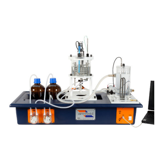
Equipment Diagrams Figure 1: Reactor Unit... -
Page 9: Important Safety Information
Supervision of users should be provided whenever appropriate. Your CEM-MKII Continuous Stirred Tank Reactor has been designed to be safe in use when installed, operated and maintained in accordance with the instructions in this manual. -
Page 10: Electrical Safety
It must be connected to a supply of the same frequency and voltage as marked on the equipment or the mains lead. If in doubt, consult a qualified electrician or contact Armfield. The equipment must not be operated with any of the panels removed. -
Page 11: Description
Description Where necessary, refer to the drawings in the Equipment Diagrams section. Overview The reactor vessel is set on a baseplate which is designed to be located on the four studs of the CEXC service unit and then secured by thumbnuts. The reactor is supported by three pillars;... - Page 12 Armfield Instruction Manual CEM MKII Continuous Stirred Tank Reactor...
-
Page 13: Installation
Installing the PC Software Before operating CEM-MKII it will be necessary to install the software from the CD- ROM supplied with CEXC onto an appropriate PC (PC not supplied). For instructions on how to install and run the software insert the CD-ROM into the optical drive on the PC (PC not supplied) then choose ‘Help’... - Page 14 Fit the conductivity probe and temperature sensor to the appropriate gland on the lid of the CEM-MKII reactor ensuring that they reach the bottom of the reactor. The gland nut should be loosened prior to fitting the probe / sensor then tightened to secure them.
- Page 15 Installation Connect the power socket at the rear of the plinth to a suitable mains electricity supply. Ensure the circuit breakers and RCD are switched to ON (up position). The on/off switch for the apparatus is located on the orange panel on the front of the plinth.
-
Page 16: Operation
Operation Where necessary, refer to the drawings in the Equipment Diagrams section. The apparatus must be set up in accordance with the Installation section. Additionally, ensure that you have read the Important Safety Information at the beginning of this manual. Operating the PC Software Details about operating the software can be obtained by choosing the ‘Help’... - Page 17 Installation of the software is described in the Installation Guide, and the software must be installed before connecting the PC to the CEXC. The software may then be run from the Start menu (Start > Programs > Armfield Chemical Reactor Software > CEM).
- Page 18 Conductivity and temperature values will be data logged when ‘GO’ is clicked. The CEM-MKII Continuous Stirred Tank Reactor can be used with the integral hot water circulator for operating temperatures above ambient. Alternatively it can be used with an optional Chiller (CW-17) for operating temperatures below ambient.
- Page 19 Operation Controlling the Hot Water Circulator (HWC) The heater is controlled by a PID controller in the software. Click ‘Hot Water Circulator’ to start the circulator pump then click ‘Control’ to open the controller window. The PID controller initially defaults to Off with the heater turned off. The Mode of Operation must be changed to Manual or Automatic as required to turn on the heater.
- Page 20 Armfield Instruction Manual Default PID Settings for the Hot Water Circulator: Process variable = Hot Water Temperature (T2) Control Variable = Heater Control Action = Reverse SP = Chosen by the user IT = 0 Cycle time = 10 PB = 1%...
-
Page 21: Equipment Specifications
Equipment Specifications Overall Dimensions Vessel diameter: 0.153m Maximum vessel depth: 0.108m Maximum volume: 2.0L Minimum vessel depth: 0.054m Minimum operating volume: 1.0L Environmental Conditions This equipment has been designed for operation in the following environmental conditions. Operation outside of these conditions may result reduced performance, damage to the equipment or hazard to the operator. -
Page 22: Routine Maintenance
CEXC manual (Routine Maintenance). Connect CEXC service unit to a PC and start up the Armfield software. Open mimic diagram screen where T1, T2 and T3 windows are displayed. - Page 23 Routine Maintenance despatch and should not require re-calibration. However, should re-calibration become necessary the appropriate calibration potentiometers can be located using the diagram below. Ensure the equipment has been connected to the electrical supply and switched on for at least 20 minutes. To access the PCB remove the cover plate on the right hand side of the plinth by unscrewing the four fixing screws.
- Page 24 Armfield Instruction Manual Immerse the probe into the Conductivity standard solution in the beaker then adjust potentiometer VR8 to give a reading of the Standard solution in the ‘Low conductivity’ window on the software. Remove the probe from the conductivity solution and rinse the probe in de- mineralised water.
-
Page 25: Laboratory Teaching Exercises
Laboratory Teaching Exercises Index to Exercises Exercise A - To find the reaction rate constant in a Continuous Stirred Tank Reactor Exercise B - To determine the effect of inadequate mixing on the reaction rate Exercise C - Determination of the Residence Time using tracer techniques Nomenclature Symbol Name Unit... -
Page 26: Common Theory
Common Theory The Armfield continuous stirred tank reactor is designed to demonstrate the mechanism of a chemical reaction in this type of reactor as well as the effects of varying the process conditions such as reaction temperature, reactor volume, stirring rate, feed rate etc. - Page 27 Ltd. for advice. Dilution of Ethyl Acetate Armfield recommends the use of a 0.1M solution of Ethyl Acetate in the CEM MkII reactor. This should be made by diluting concentrated Ethyl Acetate as follows: Therefore add 9.79ml of concentrated Ethyl Acetate to 900ml of deionised or distilled water.
-
Page 28: Exercise A - To Find The Reaction Rate Constant In A Continuous Stirred Tank Reactor
Exercise A - To find the reaction rate constant in a Continuous Stirred Tank Reactor Theory The reaction: NaOH COOC → COONa Sodium Hydroxide + Ethyl Acetate → Sodium Acetate Ethyl Alcohol can be considered equi-molar and first order with respect to both sodium hydroxide and ethyl acetate, i.e. - Page 29 However it is recommended to go through all the procedure and calculations for better understanding. On conclusion of the experiment using the Armfield data logger, a set of readings of conductivity with time will be stored in the computer. At this point, this data can be transferred onto the spreadsheet.
- Page 30 Armfield Instruction Manual Using the spreadsheet, calculate the values of from the following formulae: For the values of each of the above, the spreadsheet can be used to calculate values of sodium hydroxide concentration (a ) and sodium acetate concentration (c...
- Page 31 Exercise A To calculate the specific rate constant, k: The overall mass balance at steady-state condition may be written as: Input – Output ± Reaction = 0 i.e. for a reactant a in a reactor of volume V For the continuous reactor operating at steady state the volume may be assumed constant and mol/dm The steady state concentration of NaOH in the reactor (a...
- Page 32 Armfield Instruction Manual Once the kinetic constant at three different temperatures is known is straightforward to apply the Arrhenius law and calculate the frequency factor and the activation energy values for: Plotting Rate constant vs Temperature Obtention of the reaction rate constant in function of the temperature:...
-
Page 33: Exercise B - To Determine The Effect Of Inadequate Mixing On The Reaction Rate
Exercise B - To determine the effect of inadequate mixing on the reaction rate Theory The rate of reaction is measured by the amount of reactants converted to products in a unit of time. In order for reaction to occur, particles must come into contact and this contact must result in interaction. -
Page 34: Exercise C - Determination Of The Residence Time Using Tracer Techniques
45 minutes to 1 hour, will approach the conductivity of the feed solution and will reach the steady state. On conclusion of the experiment using the Armfield data logger, a set of readings of conductivity with time among other calculations will be stored in the computer. - Page 35 Exercise C Calculate Λ/Λ which is the equivalent to C/C where Λ is the conductivity at time t, and Λ is the conductivity of KCL at the steady state (maximum conductivity reached), for readings of t throughout the experiment. Plot this value against t and calculate the Neperian logarithm of Plot vs time and calculate the slope (straight line graph passing through the origin).
- Page 36 Armfield Instruction Manual The Average Residence Time for a working volume of 1369ml and a working flow rate of 106.5ml/min: The difference between the theoretical and the experimental value may be caused by experimental errors, such inaccuracies on the measurement of the flowrate or reactor...
-
Page 37: Contact Details For Further Information
Contact Details for Further Information Main Office: Armfield Limited Bridge House West Street Ringwood Hampshire England BH24 1DY Tel: +44 (0)1425 478781 Fax: +44 (0)1425 470916 Email: sales@armfield.co.uk support@armfield.co.uk Web: http://www.armfield.co.uk US Office: Armfield Inc. 9 Trenton - Lakewood Road...
Need help?
Do you have a question about the CEM-MKII and is the answer not in the manual?
Questions and answers