Advertisement
Quick Links
Advertisement

Related Manuals for JingYan TLL90S


Summary of Contents for JingYan TLL90S
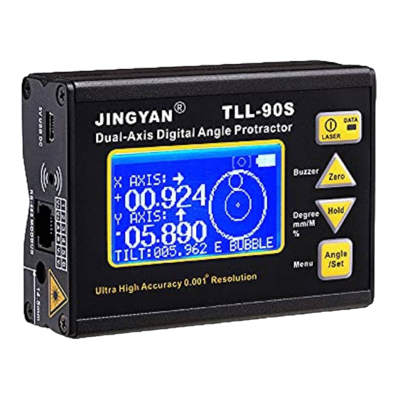
- Page 1 2014 Dec 10 TLL90S Digital Protractor User Guide...
- Page 2 2014 Dec 10 Features: 1) TLL90S: High accuracy ±0.005°, high resolution 0.001° 2) Dual and Single axis with user friendly LCD display angle 3) Laser module installed for alignment 4) Rechargeable 5) V Shape Aluminum metal case for easy to fit at the corner or pipe.
- Page 3 2014 Dec 10 Display Response time: <0.6 second Audio sound: 60dB @ 30cm Zero offset drift angle per °C: 0.002° (typical) Operating temperature: 0 to 50°C Storage temperature: -10 to 60°C User Interface: Mono-color LCD with backlight Supply Power: Rechargeable Li-Polymer 3.7V Charger port: 5V 500mA Mini type-B USB port Power Consumption:...
- Page 4 2014 Dec 10 Button Functions Function Descriptions Button Normal Mode MENU Mode This button turns the device ON. Serves as the Press and release will turn laser on/ off. escape key at Long Press for 3 seconds will turn off. menu mode When pressed, the current reading is set to zero;...
- Page 5 2014 Dec 10 Press and hold for 3 seconds to enter MENU mode, Serves as the for set mode options. Set key. Any angle measurement start button. Refer to section “Any Angle” Serves as the Press and hold for 3 seconds to enter MENU mode, Set key.
- Page 6 2014 Dec 10 Show this logo as relative value is showing. When the Zero button is pressed, the unit reset current angle to zero. Direction of tilt icons, show the tilt angle direction Dual-Axis Mode. Both the X and Y axis angle will be showed. Dual axis mode measures inclination up to +-40 degree for each axis before it automatically switch to single axis mode.
- Page 7 2014 Dec 10 computer’s USB port. This has the same effect when charging the unit with the provided adaptor. Note: When the unit is turned OFF, and plug in the USB charge cable, the LCD will no show anything, it is NORMAL. Once the unit is turned ON, the battery icon should flash indicating the unit is in charging mode.
- Page 8 2014 Dec 10 Auto Power Off For no movement in 30 minutes, the unit will power off. Or we can set to never sleep mode at below instruction. Power auto off setting: 1. Press and hold “SET” / “ANGLE” key and enter MENU mode 2.
- Page 9 2014 Dec 10 Alarming Angle setting: 1. Press and hold “SET” / “ANGLE” key and enter MENU mode 2. Select “BUZZER” by “ZERO” and “HOLD” key, press “SET” or “ANGLE” key to enter BUZZER setting Press and hold “ZERO” and “HOLD” key for fast scrolling the digit. 3.
-
Page 10: Calibration Procedure
2014 Dec 10 At Step1, you measured X and Y value, X1 and Y1 At Step2, you measured X2 and Y2, in theory X1=-X2, Y1=-Y2. If the error is too large, you can enter calibration mode to eliminate the error Accuracy drift is causing by large ambient temperature change (5 to 10 Degree Celsius) or the unit has been dropped. - Page 11 2014 Dec 10 Step 3: LCD display “CALIBRATE HORIZONTAL PRESS SET”. Place the unit horizontal like the picture “STEP 3” and then press “SET”, wait until the beep sound stop. Step 4: Then rotate the unit 180 degree at the same place. Press the “ZERO” button again, and wait for the beep finished.
- Page 12 2014 Dec 10 ANY ANGLE measurement: Any angle measurement is using gyro technique. You can measure the angle between two faces, not only in earth gravity direction. Press Angle key at the first face, and then rotate slowly and must keep the rotation axis to another testing face It will then show the angle once you not move the unit.
- Page 13 2014 Dec 10 Any Angle Measurement Method: Example: Measure angle between two wooden walls is 88.2°...
- Page 14 2014 Dec 10 Calibrate Gyro Place Unit At Flat Table And then Press Set Flip 360 degree in clockwise and then press set Please rotate slowly to increase the accuracy Place unit at flat table and then press set...
-
Page 15: Data Communication
2014 Dec 10 Flip 360 degree counter clockwise and then press set Please rotate slowly to increase the accuracy Data Communication Communication is in MODBUS format: Baud Rate 9600 Can connect up to 255 TLL90 in the same RS485 network Choose the output port 1. - Page 16 2014 Dec 10 2. Select “POWER” by “ZERO” and “HOLD” key, press “SET” key to enter Data communication 3. Scroll “USB” or “RS485” by “Zero” and “HOLD” key 4. Press “SET” key to confirm which port to communicate Set the address 1.
- Page 17 2014 Dec 10 Modbus protocol of communication Sent to read (16 bit) (example to modify display mode) Purpose 0x01 Address of device 0x03 Function read 0x00 High Byte of register address (100 Display mode) 0x66 Low Byte of register address (100 Display mode) 0x00 High Byte of number of register to read (Always 0) 0x02...
- Page 18 2014 Dec 10 Register to read Address Purpose (16 bit data) Display Single Axis 0x0064 Tilt Mode Dual Axis Degree Measuring 0x0065 mm/M format Gradient (Slope) 0x0066 High 16 bit X axis/ Single axis tilt angle: 32 bit signed integer 2’s complement 00001= 00.001 degree 0x0067 Low 16 bit...
- Page 19 2014 Dec 10 TLL90S 双轴激光水平用说明书 产品特点: 1)高精度 ±0.005°, 高分辨率 0.001° 2) 可测单轴、双轴倾斜角度,大屏 LCD 清晰显示角度。 3)激光打标...
- Page 20 2014 Dec 10 4) 充电功能 5) 外壳 V 槽设计可以轻松放置在拐角和圆管上。 6) 磁铁吸附功能 7) 可对指定角度设定蜂鸣报警 8) 可任意物体之间的角度 9) 通过 USB,蓝牙和电脑连接 10)可以用 MODBUS 485 模式连接 PLC,可同时连接 255 台 TLL-90S 产品规格 产品精度: 0 至 20°: ± (0.005°) 20 至 70°: ± (0.01°) 70 至 90°: ± (0.005°) *校正之后的精度* 测量范围: 单轴模式: 360°,...
- Page 21 2014 Dec 10 使用温度: 0 至 50°C 储存温度: -10 至 60°C 用户界面: 背光单色 LCD 供电电源: 3.7V 充电锂电池 充电器接口: 5V 500mA Mini B 型 USB 接口 产品功耗: 待机时: 10uA, 使用时: 20mA. 待机时电池续航时间: 4000 小时 使用时电池续航时间: 30 小时 尺寸 (mm): 93(长) x 66(宽) x 28(高) 磁力座: 设置在底部...
- Page 22 2014 Dec 10 按键功能 功能详解 按键 普通模式 菜单模式 功能一:按一秒开机 菜单模式下相 功能二:开机后按一秒可开启激光 当于离开功 功能三:开机后长按三秒可关机 能。 功能一:按一秒当前角度将被设置成零; 以后的 测量将以此为零基准. LCD 上会显示三角图标 在菜单模式下 当“向上”按 “ ”,提示用户现在处于 ZERO 模式下。 键 功能二:长按三秒用于设置或取消蜂鸣功能. LCD 屏幕上显示图标 “ ”。 可以对任意角度设 置蜂鸣报警。 详解查阅 “角度报警”. 功能一:按下一秒,会锁定当前角度读数。 在菜单模式下 功能二:长按三秒,可切换为三种读数模式:1) 当“向下”按 角度模式 2) mm/M 模式 3)斜度 % 模式 方便不 键...
- Page 23 2014 Dec 10 LCD 显示图标说明 电池状态指示图标:用于指示当前电池状态。分别指示电池三种状态 没电,一半 ,满电. 在双轴角度测试模式下, LCD 会显示当前图标模拟角度水泡,演示倾斜 方向. 角度模式. 闪烁时候表示进入锁定角度状态 mm/M, 将角度转换为一米外对应的高度单位是毫米. 斜度 % 模式. 在 Hold 模式下会闪烁。 显示时候表示会蜂鸣, 消失表示取消。 表示当前显示的所有角度是相对的。 当 Zero 按键按下时, 会将当前 角度设置为零角度,并依此为水平基准。 单轴角度测试模式, 模拟水泡指示当前角度倾斜方向。 双轴角度测试模式. X 和 Y 两个方向的角度同时显示. 双轴角度模式测 试范围为+-40 度,超过测试范围会自动转换到单轴角度测试模式。 单轴角度测试模式.
- Page 24 2014 Dec 10 电池充电器 该仪器使用了锂电池. 充电器标准输入电压 110V 至 240V 交流(AC), 50/60Hz, 输 出电压为 5V 直流 DC, 电流 500mA. 充电器操作步骤如下: 1) 将充电器接入直流插座, 此时红色指示灯会亮。 2) 将 USB 线接入充电器的 USB 接口。 3) 将 USB 线另一端接入水平仪。 4) 水平仪屏幕上的电池图标会闪烁表示正在充电,充电完成后图标会停止闪烁。 5) 充电时间大约为 3 小时。 水平仪也可以通过 USB 线连接至电脑进行充电,这和使用充电器的效果相同。 注意:当角度尺处于关机状态时,将角度尺连接至充电器充电时,LCD 屏幕会亮但不...
- Page 25 2014 Dec 10 LCD 图标这个闪烁: 角度锁定功能使用方法: 1. 按下“HOLD” 按键进入角度锁定功能,当前角度将锁定一直显示在屏幕上。 2. 再次按下 “HOLD” 按键即可取消角度锁定功能。 自动关机功能 半小时不用水平仪,水平仪会自动关机。 也可以通过以下操作取消自动关机功能。 自动关机功能设置方法: 1.长按“Set” 按键进入菜单模式。 2.使用”Zero”和”Hold”两个按键移动光标选择“POWER”选项, 按下 “Set” 按键进入电源设置。 3.使用 “ZERO” 和 “HOLD” 按键选择“NEVER” 或“30MIN”选项。 4. 按下“ANGLE”确认当前选择,是永不关机或者半小时自动关机。 恢复出厂设置 当您使用的角度尺感觉有异常时,可以使用恢复出厂设置对角度尺进行重置。 所有角度校准设置将全部恢复到出厂时的状态. *正常状态时候不建议恢复出厂设置。 如果是精度漂移,请对角度尺进行 校正. 在恢 复出厂设置后, 请重新校正以保证精度正常。. 恢复出厂设置方法: 1.
- Page 26 2014 Dec 10 3. 使用 “Zero” 和 “Hold ” 按键选择“YES” 或“NO” 。 4. 按下“Set ”确认当前选择。 角度报警功能 报警模式: LCD 图标: 报警角度设置方法: 1. 按住 “Set”键不要松手进入菜单模式,然后放手。 2. 使用”ZERO”和”HOLD”两个按键移动光标选择“BUZZER” 选项, 按下 “ANGLE”按键进入报警角度设置。 按住 “ZERO” 或 “HOLD” 按键不放手,快速滚动数字。 3. 按下 “SET” 确定当前设置角度。 SINGLE 垂直 /单轴角度报警模式(度) DUAL.X 水平/双轴角度报警模式...
- Page 27 2014 Dec 10 第一步, 您测量一个 X 和 Y 的角度值, X1 和 Y1 第二步, 原地旋转 180 度测量新角度值 X2 和 Y2,理论上应该得到 X1=-X2, Y1=-Y2。 如果误差过大, 你可以进入校正模式校正误差。 精度误差可能是由于过大的温度变化造成 (5 到 10 摄氏度) 或者角度尺被摔过受到 大的外力冲击。 精度校正程序: 步骤一: 长按 “SET”按键进入菜单模式. 选择“Calibration” 选项, 按 “SET”按键. 将水平仪放置在一个平整的水平面 (只要一个大致水平的平面) LCD 会显示...
- Page 28 2014 Dec 10 步骤三: LCD 屏幕显示 “CALIBRATE HORIZONTAL PRESS SET”. 请竖直放置水平尺 如图 “步骤三” 。再次按 “SET”或 “ANGLE” 按键, 等待直到蜂鸣停止发声。 步骤四: 以当前状态再次旋转 180 度放置于相同地方. 再次按 “SET” 按键, 等待 直到蜂鸣停止发声。 步骤五: LCD 屏幕显示“CALIBRATE VERTICAL PRESS SET”,开机键朝上垂直放置一 个较平的墙面上. 再次按 “SET”按键, 等待直到蜂鸣停止发声。 步骤六: 旋转 180 度依然放置垂直于墙面 (此时开机键应依然朝上).
- Page 29 2014 Dec 10 “SET”按键, 等待直到蜂鸣停止发声。至此, LCD 屏幕应该回到菜单显示状态。此时 表示校准程序完成。然后选择餐单中“Back”选项回到正常操作模 任意物体间角度测量:任意物体间角度测量运用的是陀螺仪技术。 您可以测量两个面之间的角度, 不仅仅在地球重力的方向上。. 1. 在第一个面上按“ANGLE”按键, 慢慢旋转至您需要测量的第二个面上。 2. 当你停止移动时候会显示旋转的角度。 旋转轴如图:...
- Page 30 2014 Dec 10 任意面角度测量: 例如: 测量两个夹角为 88.2°的墙。 放置在第一面墙,按下 Angle 按键, 旋转至测试位置, 保持旋转角度, LCD 显示出角度 校准陀螺仪 1) 将水平仪放置于一个较平的平面,按下“Set”按键 3 秒进入主菜单。通过 Zero 和 Hold,按键将光标移至 CALIBRATE GYRO,按下 Set 按键,进入陀螺仪校 准模式。...
- Page 31 2014 Dec 10 2) 按照提示,按下 Set 键。根据提示拿起来慢慢向右旋转 360 度然后按下“Set” 按键。请在旋转时候保持慢速以保证精度。 将水平仪放置于一个较平的平面 然后按“Set”按键 拿起来慢慢向左旋转 360 度然后按下“Set”按键。请在旋转时候保持慢速以保 证精度。当动作完成以后,按下 Set 键。完成校准。...
- Page 32 2014 Dec 10 数据传输 使用 MODBUS 的方式传输数据,格式如下: 波特率为 9600; 在同一个 RS485 网络里最多可以连接 255 个 TLL90 角度尺同时进行沟通; 1. 长按按键 “SET” / “ANGLE”,进入菜单模式; 2. 进入菜单后使用“ZERO”和“HOLD” 按键使光标箭头上下移动,将光标箭头移 动至 Data communication 选项后按下 “SET”按键进入该模式 ; 3. 使用“Zero” 和 “HOLD”按键选择需要通讯的端口,“USB” 或 “RS485” ; 4. 选择好端口后按下 “SET” 按键确认并保存。 RS485 通讯接口是一个...
- Page 33 2014 Dec 10 USB 接口: USB 接口不是使用标准的 USB 沟通协议,实际上在电脑里被模拟为一个串口。 USB 的 1 脚是电源(VBUS )电压为直流 (DC)5V USB 的 2 脚是沟通脚 D-, 相当于 RS232 的 TX 沟通脚位,电压 3.3V CMOS 沟通方式 USB 的 3 脚是沟通脚 D+, 相当于 RS232 的 RX 沟通脚位,电压 3.3V CMOS 沟通方式 USB 的...
- Page 34 2014 Dec 10 写入 (16bit) (设置测量模式的例子) 16 进制 10 进制 含义 (Hex) (Dec) 0x01 仪器的地址 0x06 功能写入 寄存器地址的高字节(High Byte)(测量模式 0x01 的地址为 300) 寄存器地址的低字节(Low Byte) (测量模式 0x2C 的地址为 300) 0x00 寄存器读写入的高字节 0x01 寄存器读写入的低字节 0x3F CRC 校验的低字节 0x88 CRC 校验的高字节 读取寄存器 地址 含义...
- Page 35 2014 Dec 10 倾斜的百分比% (45 度为 100%) 0x0066 高 16 位(bit) X 轴/ 单轴倾斜角度: 32 位带符号整数 二进制补码 00001= 00.001 度 0x0067 低 16 位(bit) 0x0068 高 16 位(bit) Y 轴/ 单轴倾斜角度: 32 位带符号整数 二进制补码 00001= 00.001 度 0x0069 低 16 位(bit) 0x006A 高...
Need help?
Do you have a question about the TLL90S and is the answer not in the manual?
Questions and answers