Table of Contents
Advertisement
Quick Links
Advertisement
Table of Contents

Related Manuals for Loup Electronics II


Summary of Contents for Loup Electronics II
- Page 1 LOUP II DRILL MONITOR OPERATION AND CALIBRATION MANUAL Issue 3.0 01/15/10...
- Page 2 Service and Technical Support Contact: Loup Electronics Inc. Address: 2960 N. 38 Street Lincoln, NE 68504 Phone: 877-489-LOUP(5687) 402-464-7131 Fax: 402-464-7104 E-mail: info@loupelectronics.com Loup Electronics 2960 North 38 Street Lincoln NE, 68504 (877)489-5687...
-
Page 3: Table Of Contents
HAFT ETTINGS 2.6.1 Pulses per Rev ......................20 2.6.2 Low Alarm Point ....................20 2.7 S ......................21 ETTINGS 2.7.1 Low Alarm Point ....................21 Loup Electronics 2960 North 38 Street Lincoln NE, 68504 (877)489-5687... - Page 4 II DM O ) ..............26 ONNECTIONS 3.3.1 Radar Connection ....................26 3.3.2 Power Connection ....................26 3.3.3 Harness Connections ..................... 27 3.4 B ....................28 ASIC IAGRAM Loup Electronics 2960 North 38 Street Lincoln NE, 68504 (877)489-5687...
-
Page 5: Operation
1.0 Operation The Loup II Drill Monitor is a full featured monitor designed to provide accurate population and seed flow information for conventional and air drills. This manual will familiarize you with operation, calibration and technical information. All aspects and features are detailed but may not be applicable to your system configuration. -
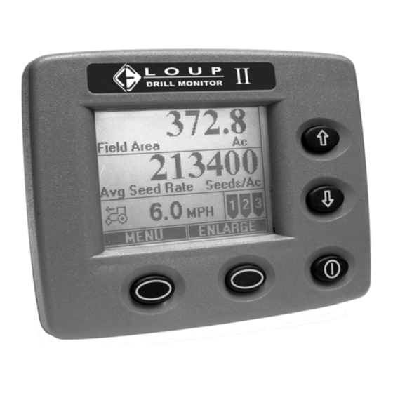
Page 6: Normal Operate Screen
The Bin Level Window is shown as 3 graphics: 1 shows a full hopper 2 shows an empty hopper 3 shows no hopper sensor present The soft key windows are displaying “Menu” and “Enlarge”. Loup Electronics 2960 North 38 Street Lincoln NE, 68504 (877)489-5687... -
Page 7: Changing Display Size
Enlarged Operate Screen 1.4 Changing Displayed Functions The display of the Loup II monitor can be changed to show any of the available functions the operator chooses. Pressing either the UP arrow or the DOWN arrow button while at the normal operate screen will allow you pick from a list of the available functions. - Page 8 Average – Displays the average seed spacing for all rows 1 – Row #1 ; 2 – Row #2 ; ect. Manual – Allows the Operator to manually scroll through all rows Loup Electronics 2960 North 38 Street Lincoln NE, 68504 (877)489-5687...
-
Page 9: Alarms
Pressing “OK” will silence all alarms. All acknowledged alarms are displayed on the normal operating screen’s active alarm window until the alarm condition is fixed. Sample alarm screens are shown on the following page. Loup Electronics 2960 North 38 Street Lincoln NE, 68504 (877)489-5687... -
Page 10: Should Be Seeding
In this example Row 2 has fallen below the low alarm point. Acknowledged Low Seed Rate displayed in active alarm window Loup Electronics 2960 North 38 Street Lincoln NE, 68504 (877)489-5687... -
Page 11: Empty Bin
Two different Blockage Module alarms may occur. Blocked: Blockage Module Run 1 is Blocked indicates the displayed row has stopped seeding and should be cleaned. Acknowledged Run Blocked alarm displayed in active alarm window Loup Electronics 2960 North 38 Street Lincoln NE, 68504 (877)489-5687... -
Page 12: Communication Error
If no loose connections are found, check all wiring to ensure the wires have not been broken Acknowledged Communication Error displayed in active alarm window If any of the listed alarms persist or if an alarm is displayed that is not listed contact Loup Electronics. Loup Electronics 2960 North 38 Street Lincoln NE, 68504 (877)489-5687... -
Page 13: Special Start-Up
If this screen appears and you are unsure of what to do contact Loup Electronics. 1.6.1 Learn New System The learn mode is a onetime process that identifies each sensor with the monitor. - Page 14 “seeing” a type of sensor other than what is required for this function. For example: This message would appear if monitor asks for Shaft 1 but a hopper sensor is plugged in. Loup Electronics 2960 North 38 Street Lincoln NE, 68504 (877)489-5687...
-
Page 15: System Settings
Wrong Sensor Type for message appears, check that all harness connections are secure. If no connections are unplugged it may be necessary to Re-Learn the system. If problems persist, contact Loup Electronics 2.0 System Settings Pressing the MENU button on the Normal Operate Screen will access your system settings. -
Page 16: Installation
Adjust accordingly to the size of your drill (i.e. 15ft, 20ft, 30ft, 40ft) 2.2.3 Clear Field Area Use to zero or clear your Field Acres 2.2.4 Clear Total Area Use to zero or clear your Total Acres Loup Electronics 2960 North 38 Street Lincoln NE, 68504 (877)489-5687... -
Page 17: Speed Settings
The monitor will not display 400 when the speed calibration is complete rather it will display the pulses counted in 400 feet. Loup Electronics 2960 North 38 Street Lincoln NE, 68504 (877)489-5687... - Page 18 400-foot 400-foot course to Exit and Save course. As you drive the pulses Note: The 235 under Wheel receive will begin counting up. Pulses Received is for illustration purposes only. Loup Electronics 2960 North 38 Street Lincoln NE, 68504 (877)489-5687...
-
Page 19: Fan Settings
The High Alarm Limit is set by the user for high rpm notification. Default is 5500 RPM. **Fan RPM above the High Alarm Point or Below the Low Alarm Point will cause an alarm condition that cannot be acknowledged. Loup Electronics 2960 North 38 Street Lincoln NE, 68504 (877)489-5687... -
Page 20: Bin Settings
2.6.2 Low Alarm Point The Low Alarm Point is set as a reference point for the alarm. If the shaft turns slower than this designated point, an alarm will sound. Loup Electronics 2960 North 38 Street Lincoln NE, 68504 (877)489-5687... -
Page 21: Seed Settings
The Population Adjust setting will influence your population by a set percentage. This should only be used if population counts are consistently low by a specific percent. Default = 0 Loup Electronics 2960 North 38 Street Lincoln NE, 68504 (877)489-5687... -
Page 22: Blockage Module Settings
A blockage calibration must be done for proper operation of the blockage sensors. This procedure should be done when changing seed rates or seed varieties i.e. Soybeans to Wheat. Procedure (Continued on next page): Loup Electronics 2960 North 38 Street Lincoln NE, 68504 (877)489-5687... - Page 23 Note: The number 32 is for illustration purposes only. Your number may be different. 4. When the Calibrated row equals the Total Calibration is complete. Press SELECT to Exit Loup Electronics 2960 North 38 Street Lincoln NE, 68504 (877)489-5687...
-
Page 24: Weight Settings
The minimum value is .5 acre and the max value is 10 acres. If seeding stops before this minimum value is attained then the Loup II Drill Monitor will not report back Calculated population, Area Left, or Applied weight information when forward travel drops below 2 MPH. -
Page 25: Global Settings
3.1 Console The console installation varies based on the operator’s personal preference and the available space for the console. Loup Electronics has attempted to keep the size of the console to a minimum to allow you to find the best location within the cab to mount your console. -
Page 26: Wire Connections
3.3 Wire Connections (Loup II DM Only) There are only four types of connections that can be made to the monitor: Power (2 ring terminals), Hitch Connection (3 pin shroud connector) and Optional Speed Connection (3 pin tower connector). 3.3.1 Radar Connection A 3-pin tower connector is available to be connected to Radar if desired. -
Page 27: Harness Connections
3.3.3 Harness Connections The Loup II drill monitor uses ‘smart sensor’ technology. This means that all of the sensors share the same wires for power, ground and communication. Sensor connection: 3-pin Packard Weather Pak Connector Pin A: +12 V (White) -
Page 28: Basic Wire Diagram
3.4 Basic Wire Diagram Loup Electronics 2960 North 38 Street Lincoln NE, 68504 (877)489-5687... - Page 29 Notes: Loup Electronics 2960 North 38 Street Lincoln NE, 68504 (877)489-5687...
Need help?
Do you have a question about the II and is the answer not in the manual?
Questions and answers