Advertisement
Mounting Installation Instructions
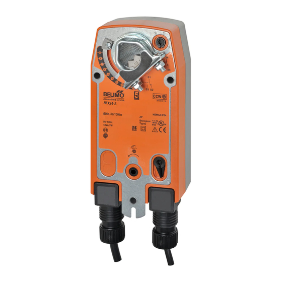
NFB, NFX Series
Features
• On/Off, 2-10 VDC, Variable MFT, Spring Return, 24 VAC
or 24 VDC, 120 VAC-240 VAC
• 90 in-lb min. torque, for control of air dampers
Dimensions (Inches [mm])
K7-2 (supplied)
1/2" Centered
3/4" Centered
(Default)
(Field Selectable)
1.05" Centered
(Field Selectable)
General Information
Application
For On/Off, VDC, programmable MFT, fail-safe control of
dampers in HVAC systems. Actuator sizing should be
done in accordance with the damper manufacturer's
specifications. Control can be on/off, 2-10 VDC or
programmable MFT.
The actuator is mounted directly to a damper shaft up to
1.05" in diameter by means of its universal clamp. A
crankarm and several mounting brackets are available
for applications where the actuator cannot be direct
coupled to the damper shaft.
Operation
The NFB, NFX series actuators provide true spring return
operation for reliable fail-safe application and positive
close off on air tight dampers. The spring return system
provides consistent torque to the damper with, and
without, power applied to the actuator.
The NFB, NFX series provides 95° of rotation and is
provided with a graduated position indicator showing
-0° to 95°. The NFB, NFX series has a unique manual
positioning mechanism which allows the setting of any
damper position within its 95° of rotation. The actuator
is shipped in the zero position (5° from full fail-safe) to
provide automatic compression against damper gaskets
for tight shutoff. When power is applied, the manual
mechanism is released. The actuator will now try to
close against the -5° position during its normal control
operations. The manual override can also be released
physically by the use of a crank supplied with the
actuator.
The NFB, NFX series use a brushless DC motor which is
controlled by an Application Specific Integrated Circuit
(ASIC). The ASIC monitors and controls the actuator's
rotation and provides a digital rotation sensing function
to prevent damage to the actuator in a stall condition.
The actuator may be stalled anywhere in its normal
rotation without the need of mechanical end switches.
The NFB...-S, NFX...-S versions are provided with two
built in auxiliary switches. These SPDT switches are
provided for safety interfacing or signaling, for example,
for fan start-up. The switching function at the fail-safe
postion is fixed at 10°, the other switch function is
adjustable between 10° to 90°.
®
Advertisement
Table of Contents

Related Manuals for Belimo NFB Series


Summary of Contents for Belimo NFB Series
- Page 1 Mounting Installation Instructions ® NFB, NFX Series General Information Application For On/Off, VDC, programmable MFT, fail-safe control of dampers in HVAC systems. Actuator sizing should be done in accordance with the damper manufacturer’s specifications. Control can be on/off, 2-10 VDC or programmable MFT.
-
Page 2: Installation Instructions
Installation Instructions ® Quick-Mount Visual Instruction for Mechanical Installation 1/4" [6.35 mm] 35° ... 95° 1/4" [6.35 mm] CCW CW 1/4" [6.35 mm] 1/4" [6.35 mm] Standard Mounting 1. Rotate the damper to its fail-safe position. If the shaft rotates counterclockwise, mount the “CCW” side of the actuator out. If it rotates clockwise, mount the actuator with the “CW”... - Page 3 Installation Instructions ® K7-2 Universal Clamp...
-
Page 4: Mechanical Installation
Instruct the installing contractor to allow space for NOTE: The NFB, NFX…series actuator is shipped mounting and service of the Belimo actuator on the shaft. with the manual override adjusted for a +5° position The damper shaft must extend at least 3 1/2” from the at the universal clamp (not at full fail-safe, 0°). - Page 5 Installation Instructions ® Mechanical Installation extends at least 1/8” through the clamp, mount the Jackshaft Installation actuator as follows. If not, go to the Short Shaft The NFB, NFX… series actuator is designed for use with Installation section. jackshafts up to 1.05” in diameter. In most applications, 3.
- Page 6 Installation Instructions ® Mechanical Installation Rotation Limitation The angle of rotation limiter, which is built into the actuator, is used in conjunction with the tab on the universal clamp or IND-AFB position indicator. In order to function properly, the clamp or indicator must be mounted correctly.
- Page 7 Installation Instructions ® Mechanical Installation Manual Override Testing the Installation Without Power The actuator/damper installation may be tested without The NFB, NFX series actuators can be manually power at the actuator. Refer to the manual positioning positioned to ease installation or for emergency section of the instructions.
- Page 8 Installation Instructions ® Mechanical Installation and Non-Direct Mounting Methods Method 2 - See Figure G KH-AFB Crank Arm 1. Position the damper to the point at which you want Including Retaining Ring the switch to activate. This may be done by using the manual override or by providing the appropriate CAUTION: The retaining clip supplied with the clamp is proportional signal to NFB24, NFX24…...
-
Page 9: Electrical Operation
The electromagnetic poles are switched by a special ASIC circuit developed by Belimo. Unlike the conventional DC motor, there are no brushes to wear or commutators to foul. Overload Protection The NFB, NFX series actuators are protected from overload at all angles of rotation. -
Page 10: General Wiring Instructions
Follow all instructions in this literature. If you have any questions, contact the controller manufacturer and/or Belimo. Multiple Actuators, Multiple Transformers Multiple actuators positioned by the same control signal Transformers... - Page 11 Installation Instructions ® General Wiring Instructions Wire Type and Wire Installation Tips For most installations, 18 or 16 Ga. cable works well with the NFB24, NFX24... actuators. Use code-approved wire nuts, terminal strips or solderless connectors where wires are joined. It is good practice to run control wires unspliced from the actuator to the controller.
- Page 12 Wiring ® On/Off, 24V Control Input Power Power Control Position Auxiliary Custom Running Time Supply Consumption Input Feedback Switches Options Spring Return ♦ NFB24 <75 <20 6.0 (2.5) ♦ NFB24-S <75 <20 6.0 (2.5) ♦ NFX24 <75 <20...
- Page 13 Wiring ® On/Off, Universal Power Supply Control Input Power Power Control Position Auxiliary Custom Running Time Supply Consumption Input Feedback Switches Options Spring Return ♦ NFBUP <75 <20 6.5* 6.0 (2.5) ♦ NFBUP-S <75 <20 6.5* 6.0 (2.5) ...
- Page 14 Wiring ® 2 to 10 VDC, 24V Control Input Power Power Control Position Auxiliary Custom Running Time Supply Consumption Input Feedback Switches Options Spring Return ♦ NFB24-SR <20 3.5 (2.5) ♦ NFB24-SR-S <20 3.5 (2.5) ...
- Page 15 Wiring ® MFT, 24V Control Input Power Power Control Position Auxiliary Custom Running Time Supply Consumption Input Feedback Switches Options ♦ <60 sec @ -22°F [-30°C]. Spring Return 40...220 ♦ NFB24-MFT <20 6.5 (3.0) ...
-
Page 16: Start-Up And Checkout
• If multiple transformers are used with one control signal, make sure all No. 1 wires are tied together and tied to control signal negative (-). • Controllers and actuators must have separate 24 VAC/VDC power sources. Note 2 If failure occurs within 5 years from original purchase date, notify Belimo and give details of the application.
Need help?
Do you have a question about the NFB Series and is the answer not in the manual?
Questions and answers