
Related Manuals for COMEPI MS1A31-024

Summary of Contents for COMEPI MS1A31-024
- Page 1 MS Safety Modules Instruction manual Manuale d’istruzione Betriebsanleitung Manuel d’instructions Manual de instrucciones Brugervejledning 使用手册 COMEPI srl Via Novarino 9/L , 23899 Robbiate (lecco) Italy...
-
Page 2: Table Of Contents
6.5.2 E-stop, safety limit switch and safety interlocks (single channel mode) ......................15 6.5.3 E-gate and safety non-contact switches ..................................15 6.5.4 Lift levelling application ........................................16 MS1A31-024 ................................................18 7.1 Terminal layout ............................................18 7.2 Operating modes ............................................18 7.2.1 Manual start ............................................ - Page 3 10.3.5 Inputs ..............................................39 10.3.6 Outputs ..............................................40 10.3.7 Compatibility and conformity ..................................... 40 10.3.8 Environmental ........................................... 40 LED information ..............................................41 Total current Σ Ith² ............................................. 42 Rev. 1 | 01/2020 | MS Safety Module | © 2020 | Comepi srl...
- Page 4 Maintenance and repairs The device contains no parts that require maintenance. In case of failure, do not open the device; the device must be sent to COMEPI branch or distributor. Rev. 1 | 01/2020 | MS Safety Module | © 2020 |...
-
Page 5: Introduction
The MS1 modules provide a safety-related interruption of a safety circuit. The safety modules are compliant with the requirements of EN ISO 13849-1 and EN 81-20 and EN 81-50 (only MS1A31-024 and MS1A20-024) and may be used in applications with:... -
Page 6: Safety
Comepi is not responsible for these operations or for any risks in connection with them. Reference should be made to the manual and to the relative product and/or application standards to ensure correct use of any devices connected to the MS1 module within the speci c application. -
Page 7: Installation And Environmental Conditions
MS1 must only be used within an ambient temperature range of -25 ÷ +60°C (-13 ÷ +140°F); UL: +40°C (+104°F), away from any condensation or conducting uids. To avoid possible interference, keep the connecting conductors separate from the power conductors. Rev. 1 | 01/2020 | MS Safety Module | © 2020 | Comepi srl... -
Page 8: Wiring
Once the wiring of the terminal block is completed, insert the terminal block into the respective position The plug-in terminal blocks are coded, so to prevent inserting the terminal blocks in the wrong position. Rev. 1 | 01/2020 | MS Safety Module | © 2020 | Comepi srl... -
Page 9: Devices
MS1 modules are compliant with international standards, designed to provide the most comprehensive protection for equipment and personnel. They enable safety functions, accepting di erent types of inputs. MS1 safety modules and expansion unit provide for safety instantaneous relay outputs. MS1A20-024 MS1A31-024 MS1B31-024 MS1H21-024 MS1E41-024... -
Page 10: Ms1A20-024
A new operating cycle is possible only after releasing both input contacts and then operating them again Reset / Start Input ch 1 Input ch 2 Safety output ∞ <160ms <20ms Rev. 1 | 01/2020 | MS Safety Module | © 2020 | Comepi srl... -
Page 11: Automatic Start
Reset / Start Input ch 1 Input ch 2 Safety output Ts Td > 500ms < 500ms ∞ <160ms <20ms Rev. 1 | 01/2020 | MS Safety Module | © 2020 | Comepi srl... -
Page 12: Technical Data
24 Vdc ±10%, 2 W, Class 2 24 Vac -15/+10% 50÷60 Hz, 4.5 VA, Class 2 Power supply Overvoltage category III Short circuit protection internal PTC Rated insulation voltage 4 kV Rev. 1 | 01/2020 | MS Safety Module | © 2020 | Comepi srl... -
Page 13: Inputs
Electromagnetic compatibility. Product family standard for lifts, EN 12015 escalators and passenger. Emission Electromagnetic compatibility. Product family standard for lifts, EN 12016 escalators and passenger. Immunity Approvals Rev. 1 | 01/2020 | MS Safety Module | © 2020 | Comepi srl... -
Page 14: Environmental
6.5.1 E-stop, safety limit switch and safety interlocks (double channel mode) In case of a fault the safety outputs will switch OFF E-STOP Pwr 24V (+/~) Pwr 24V (-/~) Manual start Rev. 1 | 01/2020 | MS Safety Module | © 2020 | Comepi srl... -
Page 15: E-Stop, Safety Limit Switch And Safety Interlocks (Single Channel Mode)
6.5.3 E-gate and safety non-contact switches In case of a fault the safety outputs will switch OFF Sensor 1 E-gate Sensor 2 Pwr 24V (+/~) Pwr 24V (-/~) Manual start Rev. 1 | 01/2020 | MS Safety Module | © 2020 | Comepi srl... -
Page 16: Lift Levelling Application
EN 81-20: Safety rules for the construction and installation of lifts. Part 20: passenger and goods/passenger lifts. EN 81-50: Safety rules for the construction and installation of lifts. Part 50: design rules, calculations, examinations and tests of lift components. Rev. 1 | 01/2020 | MS Safety Module | © 2020 | Comepi srl... - Page 17 EN 81-20: Safety rules for the construction and installation of lifts. Part 20: passenger and goods/passenger lifts. EN 81-50: Safety rules for the construction and installation of lifts. Part 50: design rules, calculations, examinations and tests of lift components. Rev. 1 | 01/2020 | MS Safety Module | © 2020 | Comepi srl...
-
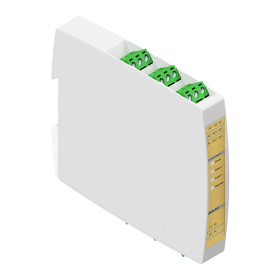
Page 18: Ms1A31-024
The MS1A31-024 module monitors emergency stops, limit switches, magnetic switches according to 2006/42/CE Machinery Directives. The MS1A31-024 is also used for oor levelling and relevelling of lift cabin, according to the 2014/33/EU Lift Directive, in lift applications. 7.1 Terminal layout... -
Page 19: Automatic Start
Reset / Start Input ch 1 Input ch 2 Safety output Auxiliary output Ts Td > 500ms < 500ms ∞ <160ms <20ms Rev. 1 | 01/2020 | MS Safety Module | © 2020 | Comepi srl... -
Page 20: Technical Data
24 Vdc ±10%, 2 W, Class 2 24 Vac -15/+10% 50÷60 Hz, 4.5 VA, Class 2 Power supply Overvoltage category III Short circuit protection internal PTC Rated insulation voltage 4 kV Rev. 1 | 01/2020 | MS Safety Module | © 2020 | Comepi srl... -
Page 21: Inputs
Electromagnetic compatibility. Product family standard for lifts, EN 12015 escalators and passenger. Emission Electromagnetic compatibility. Product family standard for lifts, EN 12016 escalators and passenger. Immunity Approvals Rev. 1 | 01/2020 | MS Safety Module | © 2020 | Comepi srl... -
Page 22: Environmental
E-stop, safety limit switch and safety interlocks (double channel mode) In case of a fault the safety outputs will switch OFF E-STOP Pwr 24V (+/~) Pwr 24V (-/~) Manual start Rev. 1 | 01/2020 | MS Safety Module | © 2020 | Comepi srl... -
Page 23: E-Stop, Safety Limit Switch And Safety Interlocks (Single Channel Mode)
7.5.3 E-gate and safety non-contact switches In case of a fault the safety outputs will switch OFF Sensor 1 E-gate Sensor 2 Pwr 24V (+/~) Pwr 24V (-/~) Manual start Rev. 1 | 01/2020 | MS Safety Module | © 2020 | Comepi srl... -
Page 24: Lift Levelling Application
7.5.4 Lift levelling application The MS1A31-024 is designed to be employed in lift plants for oor levelling and relevelling of the cabin, according to the requirements of EN 81-20 and EN 81-50 Standards, and according to the 2014/33/EU Lift Directive. - Page 25 EN 81-20: Safety rules for the construction and installation of lifts. Part 20: passenger and goods/passenger lifts. EN 81-50: Safety rules for the construction and installation of lifts. Part 50: design rules, calculations, examinations and tests of lift components. Rev. 1 | 01/2020 | MS Safety Module | © 2020 | Comepi srl...
-
Page 26: Ms1B31-024
A new operating cycle is possible only after releasing both input contacts and then operating them again Reset / Start Input ch 1 Input ch 2 Safety output Auxiliary output ∞ <160ms <20ms Rev. 1 | 01/2020 | MS Safety Module | © 2020 | Comepi srl... -
Page 27: Automatic Start
Reset / Start Input ch 1 Input ch 2 Safety output Auxiliary output Ts Td > 500ms < 500ms ∞ <160ms <20ms Rev. 1 | 01/2020 | MS Safety Module | © 2020 | Comepi srl... -
Page 28: Technical Data
Rated insulation voltage 4 kV 8.3.5 Inputs Number of safety channels Safety inputs (contact inputs) S11-S12 and S21-S22 Loop resistance Max. 1 k Input current Typical 5 mA Rev. 1 | 01/2020 | MS Safety Module | © 2020 | Comepi srl... -
Page 29: Outputs
You must comply with the safety-related parameteres in order to ensure the required safety level for your plant/machine. All the units which use a safety function must be considered when calculating the overall safety level. Rev. 1 | 01/2020 | MS Safety Module | © 2020 | Comepi srl... -
Page 30: Function Description
E-gate, safety limit switch and one access monitoring (double channel mode) In case of a fault the safety outputs will switch OFF Pwr 24V (+/~) Pwr 24V (-/~) Manual start Rev. 1 | 01/2020 | MS Safety Module | © 2020 | Comepi srl... -
Page 31: E-Gate, Safety Limit Switch And Two Accesses Monitoring (Double Channel Mode)
E-gate, safety limit switch and one access monitoring (single channel mode) In case of a fault the safety outputs will switch OFF Pwr 24V (+/~) Pwr 24V (-/~) Manual start Rev. 1 | 01/2020 | MS Safety Module | © 2020 | Comepi srl... -
Page 32: Ms1H21-024
NC auxiliary output to the close state and PNP auxiliary output is OFF A new operating cycle is possible only after releasing both push buttons and operating them again Rev. 1 | 01/2020 | MS Safety Module | © 2020 | Comepi srl... -
Page 33: Technical Data
24 Vdc ±10%, 2 W, Class 2 24 Vac -15/+10% 50÷60 Hz, 4.5 VA, Class 2 Power supply Overvoltage category III Short circuit protection internal PTC Rated insulation voltage 4 kV Rev. 1 | 01/2020 | MS Safety Module | © 2020 | Comepi srl... -
Page 34: Inputs
Electrical equipment for measurement, control and laboratory use. EMC requirements. Immunity requirements for safety-related systems and EN 61326-3-1 for equipment intended to perform safety-related functions (functional safety) - General industrial applications Approvals Rev. 1 | 01/2020 | MS Safety Module | © 2020 | Comepi srl... -
Page 35: Environmental
Cat 4; PLe, possible (also depending on the output wiring and the chosen trigger elements). Pwr 24V (+/~) Pwr 24V (-/~) 24Vdc Load > 2.4k Feedback control loop Rev. 1 | 01/2020 | MS Safety Module | © 2020 | Comepi srl... -
Page 36: Ms1E41-024
The opening of the safety relay output of the master module forces immediately the safety outputs of MS1E41-024 to the open state, and the NC feedback output to the close state. Feedback signal Master module Pwr 24V (+/~) Pwr 24V (-/~) Rev. 1 | 01/2020 | MS Safety Module | © 2020 | Comepi srl... -
Page 37: Extension Module In Double Channel Mode
The NO safety outputs of MS1E41-024 will switch ON again if both input 1 and input 2 are activated. Start Feedback signal master module Pwr 24V (+/~) Pwr 24V (-/~) Input ch 1 Input ch 2 Safety output Feedback output <60ms <30ms Rev. 1 | 01/2020 | MS Safety Module | © 2020 | Comepi srl... -
Page 38: Extension Module For Ms2/Mt2 Safety Modules With Ossd Safety Outpout
OSSD outputs Pwr 24Vdc Pwr 24Vdc (-) Input ch 1 Input ch 2 Safety output Feedback output Test output of MS2/MT2 <60ms <0.5ms <30ms Rev. 1 | 01/2020 | MS Safety Module | © 2020 | Comepi srl... -
Page 39: Technical Data
Number of safety channels Safety inputs (contact inputs) S11-S12 and S21-S22 Loop resistance Max. 1 k Input voltage 0 - 35 VDC Input current Typical 5 mA Rev. 1 | 01/2020 | MS Safety Module | © 2020 | Comepi srl... -
Page 40: Outputs
Operating Temperature -25 ÷ +60°C (-13 ÷ 140°F), UL: +40°C (104°F); Storage Temperature -30 ÷ +70°C (-22 ÷ 158°F) Ambient humidity range R.H. ≤95% non condensing Rev. 1 | 01/2020 | MS Safety Module | © 2020 | Comepi srl... -
Page 41: Led Information
The NO safety outputs are open and the NC auxiliary output is closed Green The NO safety outputs are closed and the NC auxiliary output is open Rev. 1 | 01/2020 | MS Safety Module | © 2020 | Comepi srl... -
Page 42: Total Current Σ Ith²
Σ Ith² 12. Total current Quadratic total current [A²] = Output 1 current[A]² + Output 2 current[A]² + Output n current[A]² Rev. 1 | 01/2020 | MS Safety Module | © 2020 | Comepi srl...
Need help?
Do you have a question about the MS1A31-024 and is the answer not in the manual?
Questions and answers