Table of Contents
Advertisement
Quick Links
OPERATOR'S MANUAL
BEVELLING MACHINE
BM25 BEVELLING MACHINE
BM-25
OPERATOR'S MANUAL
ul. Elewatorska 23/1, 15-620 Białystok
PART NO. WA-BM25
Ver: 1.3
Phone: +48 85 678-34-95, Fax: +48 85 662-78-77
www.promotech.eu
e-mail:
info@promotech.eu
TO PREVENT SERIOUS INJURY OR DAMAGE TO YOUR WATER PUMP, READ
!
!
AND UNDERSTAND ALL WARNINGS AND INSTRUCTIONS BEFORE USE
www.itmtools.com.au
Advertisement
Table of Contents

Related Manuals for Itm BM25


Summary of Contents for Itm BM25
- Page 1 OPERATOR’S MANUAL BEVELLING MACHINE BM25 BEVELLING MACHINE BM-25 OPERATOR’S MANUAL ul. Elewatorska 23/1, 15-620 Białystok PART NO. WA-BM25 Ver: 1.3 Phone: +48 85 678-34-95, Fax: +48 85 662-78-77 www.promotech.eu e-mail: info@promotech.eu TO PREVENT SERIOUS INJURY OR DAMAGE TO YOUR WATER PUMP, READ AND UNDERSTAND ALL WARNINGS AND INSTRUCTIONS BEFORE USE www.itmtools.com.au...
-
Page 2: Table Of Contents
BM25 BEVELLING MACHINE OPERATOR’S MANUAL Contents TABLE OF CONTENTS 1. GENERAL INFORMATION ....................3 1.1. Application ......................... 3 1.2. Technical data......................3 1.3. Dimensions ........................ 4 1.4. Equipment included ....................5 1.5. Design ........................6 2. SAFETY PRECAUTIONS ....................7 3. -
Page 3: General Information
BM25 BEVELLING MACHINE OPERATOR’S MANUAL BM-25 BM-25 1. GENERAL INFORMATION 1. GENERAL INFORMATION 1.1. Application 1.1. Application The BM-25 is a beveling machine designed to bevel plates made of non-alloy steel. The BM-25 is a beveling machine designed to bevel plates made of non-alloy steel. -
Page 4: Dimensions
BM25 BEVELLING MACHINE OPERATOR’S MANUAL BM-25 1.3. Dimensions www.itmtools.com.au This document is protected by copyrights. -
Page 5: Equipment Included
BM25 BEVELLING MACHINE OPERATOR’S MANUAL BM-25 1.4. Equipment included 1 Beveling machine 1 unit 2 Plastic box 1 unit 3 Guard 45° 1 unit 4 Guard 30° 1 unit 5 Grease 1 unit 6 Drift 1 unit 7 Combination wrench 22 mm... -
Page 6: Design
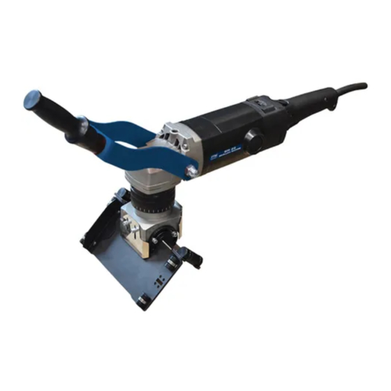
BM25 BEVELLING MACHINE OPERATOR’S MANUAL BM-25 1.5. Design Switch lock Speed knob Handle Air vents Bevel depth knob Clamping lever Chip guard Vertical guide roller Horizontal guide roller Handle Guide unit Power switch (ON/OFF) Horizontal guide Vertical guide Milling head This document is protected by copyrights. -
Page 7: Safety Precautions
BM25 BEVELLING MACHINE OPERATOR’S MANUAL BM-25 2. SAFETY PRECAUTIONS 1. Before use, read this Operator’s Manual and complete a training in occupational health and safety. 2. Use only in applications specified in this Operator’s Manual. 3. Make sure that the machine has all parts and they are genuine and not damaged. - Page 8 BM25 BEVELLING MACHINE OPERATOR’S MANUAL BM-25 21. After use, clean the machine and the milling head with a dry cotton cloth and without any chemical agents. Do not remove chips with bare hands. 22. Maintain the machine and attach/remove parts and tool only after you unplug the machine from the power source.
-
Page 9: Symbols
BM25 BEVELLING MACHINE OPERATOR’S MANUAL BM-25 3. SYMBOLS Before using the machine, familiarize yourself with the following symbols (tab. 1). Use eyes protection Use hearing protection Read the Operator’s Manual Warning against electric voltage Tab. 1. Explanation of symbols www.itmtools.com.au... -
Page 10: Startup And Operation
BM25 BEVELLING MACHINE OPERATOR’S MANUAL BM-25 4. STARTUP AND OPERATION 4.1. Handle installation The beveling machine is delivered with dismantled handle. In order to install the handle after unpacking the machine proceed as below. Unscrew the domed nut from the threaded mandrels (1). Remove the spring washers from the threaded mandrels (2). -
Page 11: Handle Adjustment
BM25 BEVELLING MACHINE OPERATOR’S MANUAL BM-25 4.2. Handle adjustment The beveling machine handle may be adjusted in three axes so the operator may adapt it to their needs. To adjust, loosen the domed nuts (1) and screws (2) and (3) using 22 mm flat wrench. -
Page 12: Beveling Angle Adjustment
BM25 BEVELLING MACHINE OPERATOR’S MANUAL BM-25 4.3. Beveling angle adjustment Unplug the power cord. Loosen the screws (1) on both sides of the guide unit and lift the guards (2). Then loosen the screws (3) on both sides of the scale and guide unit and set the required bevel angle (4). -
Page 13: Horizontal Guide Guards
BM25 BEVELLING MACHINE OPERATOR’S MANUAL BM-25 4.4. Horizontal guide guards During operation with beveling angles of 30° and 45° it is required to use the horizontal guide guards dedicated for those angles. To replace the guard proceed as below. Remove the hexagon socket head screws (1). Remove the basic guard (2). Install guard (3) or (4) according to the machining angle. -
Page 14: Vertical Guide Guard
BM25 BEVELLING MACHINE BM-25 OPERATOR’S MANUAL 4.5. Vertical guide guard Pay attention during adjustment of the vertical guide guard that the distance between the guide and the guard should be approx. 5-6 mm. It allows for free falling of chips without their accumulation behind the guard. -
Page 15: Beveling Depth Adjustment
BM25 BEVELLING MACHINE OPERATOR’S MANUAL BM-25 4.6. Beveling depth adjustment Unplug the power cord. Release the lever (1). Rotate the knob (2) so that the scale (3) shows the bevel depth “d” (max. 12.5 mm) related to the required bevel width “b” (max. -
Page 16: Cutting Inserts Installation
BM25 BEVELLING MACHINE BM-25 OPERATOR’S MANUAL 4.7. Cutting inserts installation Unplug the power cord. Remove the screws (1) and guards (2) on both sides of the guide unit. Position the guides in such way that the horizontal guide is parallel to the machine body (1) (value of 90°... -
Page 17: Replacing The Cutting Inserts
BM25 BEVELLING MACHINE BM-25 OPERATOR’S MANUAL Prepare screws (1) covered with delivered grease. Put the insert (2) in the socket, press it down and fix with screw, using T15 torx screwdriver. Make sure that the whole bottom of the insert touches the socket. -
Page 18: Turning The Guide Unit
BM25 BEVELLING MACHINE OPERATOR’S MANUAL BM-25 4.9. Turning the guide unit Unplug the power cord. Release the lever (1). Hold the bevel depth knob (2) so it does not rotate in relation to the guide unit and turn the guide unit to the desired position (3). -
Page 19: Positioning The Horizontal Guide Rollers
BM25 BEVELLING MACHINE OPERATOR’S MANUAL BM-25 4.10. Positioning the horizontal guide rollers When width of the workpiece is below 110 mm, the rollers on the horizontal guide may be set in position suitable for that width. Remove four hexagon socket head screws (1) of the roller to be moved. Move the roller (2) to desired position. -
Page 20: Operating
BM25 BEVELLING MACHINE OPERATOR’S MANUAL BM-25 4.12. Operating For the best results and optimum work, height of the workpiece above the surface on which the operator stands should be approx. 70 cm, however, it depends on the operator’s height. It allows the operator to work with slightly bent arms for lower tiredness and better pressing force. - Page 21 BM25 BEVELLING MACHINE OPERATOR’S MANUAL BM-25 Connect the machine to the power source. Make sure that the workpiece is stable. Remove all contamination from the workpiece surface. Put the machine on the left side of workpiece as shown in the figure.
- Page 22 BM25 BEVELLING MACHINE OPERATOR’S MANUAL BM-25 Start with making small widths (3-4 mm, 0.12–0.16″) and increase them with experience. Refer to the table for the recommended maximum number of passes to do depending on the bevel width. Bevel width ‘b’...
- Page 23 BM25 BEVELLING MACHINE OPERATOR’S MANUAL BM-25 a) Hold the machine firmly and keep your body and arms in a position to absorb the kickback force. By following the suitable safety measures the operator may control the kickback force. b) Maintain special caution when working in the area of corners, sharp edges, etc.
-
Page 24: Bevel Width
BM25 BEVELLING MACHINE OPERATOR’S MANUAL BM-25 4.13. Bevel width The following tables show the calculated bevel widths (in mm and inches) obtained for the individual angle of inclination and depth values. To determine the exact width, perform a test machining and correct the setting if necessary. - Page 25 BM25 BEVELLING MACHINE OPERATOR’S MANUAL BM-25 Angle [°] 15 20 25 30 35 40 45 50 55 60 65 70 75 0.5 0.1 0.1 0.1 0.0 0.0 0.0 0.0 0.0 0.0 0.0 0.1 0.1 0.1 1.0 0.2 0.1 0.1 0.1 0.1 0.1 0.1 0.1 0.1 0.1 0.1 0.1 0.2 1.5 0.2 0.2 0.2 0.1 0.1 0.1 0.1 0.1 0.1 0.1 0.2 0.2 0.2...
-
Page 26: Working At Angle Of 0
BM25 BEVELLING MACHINE OPERATOR’S MANUAL BM-25 4.14. Working at angle of 0° Levelling in order to obtain the even surface up to 2-3 mm 4.15. Working at angle of 90° Removing coatings from the surface Decreasing the sheet edge height 15 mm –... -
Page 27: Head Disassembly
BM25 BEVELLING MACHINE OPERATOR’S MANUAL BM-25 4.16. Head disassembly Before disassembly remove chips from the guides. Failure to do so may result in contamination of thread in the guide unit. When it is required to disassemble the guide unit proceed as below. - Page 28 BM25 BEVELLING MACHINE OPERATOR’S MANUAL BM-25 To assemble the head proceed in the opposite sequence as during the disassembly. Make sure that the milling head is aligned with the spindle. 10 mm www.itmtools.com.au This document is protected by copyrights.
-
Page 29: Replacing The Brushes
BM25 BEVELLING MACHINE OPERATOR’S MANUAL BM-25 4.17. Replacing the brushes Every 200 work hours check the condition of the brushes. To do this, unplug the power cord and then remove the cap and the brush. If the brush is shorter than 10 mm (0.4″), replace both brushes with new ones. -
Page 30: Declaration Of Conformity
BM25 BEVELLING MACHINE OPERATOR’S MANUAL LIMITED WARRANTY Industrial Tool & Machinery Sales (hereinafter referred to as ITMS) will, within twelve (12) months from the original date of purchase, repair or replace any goods found to be defective in materials or workmanship.
Need help?
Do you have a question about the BM25 and is the answer not in the manual?
Questions and answers