Table of Contents
Advertisement
Quick Links
CK150-4 operation
The CK150-4 is fully automatic once installed properly. The LED
indicator lights inform the user of the progress of the charging
cycle and confirm proper connections.
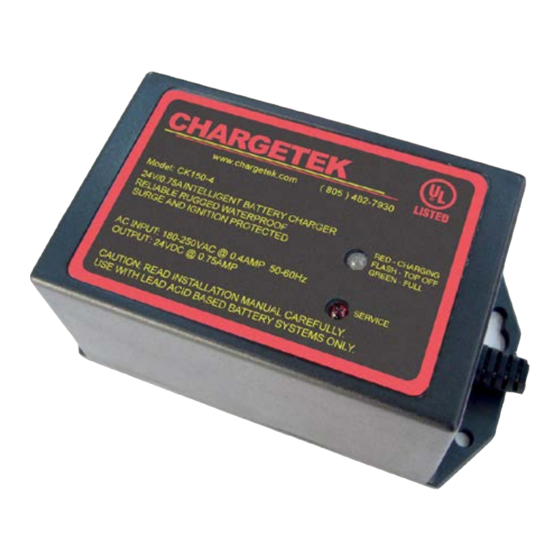
CK150-4 LED indicators
The dual color charging mode light indicates the state of charge
of the battery. The light will illuminate only when the charger is
properly connected to the battery and AC power is applied. Red
indicates bulk charging, flashing red/green indicates absorbtion
or topping off, while green indicates the battery is fully charged.
Please review the table below for electrical specifications.
PARAMETER DESCRIPTION / CONDITIONS
MIN
NOM
V
Fast charge voltage, 25C
28.8
29.0
FSTERM
V
Float voltage, I
< 1.0 A, 25 C
26.8
27.0
FLOAT
OUT
I
Fast charge, V
= 12V
0.9
FS
BATTERY
I
Float charge termination current
0.4
0.5
FLTERM
V
RMS AC voltage range
180
240
AC
I
Standby current, AC off
SBY
The CK150-4 must be connected to the battery in order for the
LEDs to illuminate. Should no illumination appear, unplug the
unit and recheck battery connections to ensure proper polarity.
The red wire connects to the positive and the black to the nega-
tive battery terminal.
If the charger is left for extended periods of time, it is advisable
to check to be certain that the green light is on and the battery
voltage is less than 27.2VDC.
Over Temperature: The CK150-4 will reduce its charging current
as its case temperature increases to insure proper operation.
In the event of a charger over temperature, the unit will turn off
until it cools and then restart automatically.
3/6/13 Ver. D
CT150-4 operation
The fully automatic CT150-4 is designed to maintain a fully
charged battery. The green LED indicator light will illuminate
indicating that the charger is properly plugged in and connected
to the battery. The green light will only illuminate once the unit
has been connected to the battery. If no light appears, unplug
the unit and recheck battery connections to ensure proper po-
larity. The red wire connects to the positive and the black to the
negative battery terminal.
Please review the table below for electrical specifications.
PARAMETER DESCRIPTION / CONDITIONS
V
Float voltage, I
< 1.0 A, 25 C
MAX
UNITS
FLOAT
OUT
29.1
VDC
I
Fast charge, V
= 12V
FS
BATTERY
27.2
VDC
V
RMS AC voltage range
AC
1.0
Amps
I
Standby current, AC off
SBY
0.6
Amps
Outline and mounting
264
VAC
6.000
0.5
ma
5.250
.21 x 2
.44 x 2
3.170
1.750
.21 x 2
4.544
AC Input
DC Output
Cord
Cord
2.580
.160
6.000
Dimensions in inches
LIMITED WARRANTY
For two years from date of purchase, Chargetek Inc. will
at its discretion repair or replace for the original consumer,
free of charge, any part or parts found to be defective by
Chargetek in workmanship or material. All shipping charges
under this warranty must be paid by the consumer. Proof
of purchase is required.
There is no other expressed warranty. Implied warranties,
including those of merchantability and fitness for a particular
purpose are limited to two years from the date of purchase.
This is the exclusive remedy and consequential damages
are excluded where permitted by law.
MIN
NOM
MAX
UNITS
26.8
27.0
27.2
VDC
1.0
1.2
1.5
Amps
180
240
264
VAC
0.5
ma
2.580
2.764
3.170
1.590
Please read the entire installation manual
before installing the battery charger. If there
are any questions or concerns, please email
us or call our toll-free number given below.
The CT150-4 and CK150-4 UL/CSA 1236 cer-
tified battery chargers are totally waterproof
and precisely regulated. They are designed
to be portable or permanently mounted on al-
most any type of vehicle including generators,
ATVs, RVs, lawn and garden tractors, snow-
mobiles, motorcycles, personal watercraft and
409 Calle San Pablo, Unit 104, Camarillo, CA 93012 ~ Phone: (866) 482-7930 ~ Fax: (805) 482-7936
CT150-4 / CK150-4
Installation Manual
boats. This product line is particularly suited
for storage, security, standby and remote ap-
plications. The charger can be left connected
to the battery indefinitely.
The CK150-4 is a three stage charger with a
sophisticated microprocessor control. It en-
sures that the battery is recharged with preci-
sion and will be restored to its full capacity as
fast as possible while prolonging its life. The
chargers are rugged, reliable and completely
automatic.
Chargetek
www.chargetek.com
Advertisement
Table of Contents

Related Manuals for Chargetek CK150-4


Summary of Contents for Chargetek CK150-4
- Page 1 2.764 3.170 3.170 1.750 1.590 The CK150-4 must be connected to the battery in order for the LEDs to illuminate. Should no illumination appear, unplug the .21 x 2 unit and recheck battery connections to ensure proper polarity. 4.544 The red wire connects to the positive and the black to the nega- tive battery terminal.
- Page 2 Save these instructions. The CK150-4 employs a three stage charge routine. This is the The charger will operate properly with either 220 volts 50 Hz charging procedure most lead-acid battery manufacturers rec- or 220 volts 60 Hz AC input.
Need help?
Do you have a question about the CK150-4 and is the answer not in the manual?
Questions and answers