Table of Contents
Advertisement
Quick Links
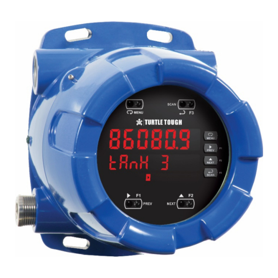
DSS EX Explosion-Proof Transmitter & Controller
Instruction Manual
• Modbus
®
RTU Master, Slave, or Snooper Mode
• Poll and Display up to 16 Process Variables
• Two (2) 0-20 mA, 4-20 mA, 0-5 V, 1-5 V, and ±10 V Inputs
• Math functions Capabilities
• Isolated 24 VDC @ 25 mA Transmitter Power Supply
• Multi-Pump Alternation Control
• Signal Input Conditioning for Flow & Round Horizontal Tank
• Programmable Displays & Function Keys
• 32-Point, Square Root, or Exponential Linearization
• Up to Three 4-20 mA Analog Outputs Available
• Modern, Sleek and Practical Enclosure
• Display Mountable at 0°, 90°, 180°, & 270° Degrees
• Explosion-Proof, IP68, NEMA 4X Enclosure
• SafeTouch
®
Through-Glass Button Programming
• Flanges for Wall or Pipe Mounting
• Superluminous Sunlight Readable Display
• Free USB Programming Software & Cable
TURTLE TOUGH
Unit 12, 634-644 Mitcham Rd
Phone:
+1-909-547-3300
• Email:
•
Vermont VIC 3133 Australia
info@turtletoughsensors.com
Modbus Transmitter/Controller
www.turtletoughsensors.com
Advertisement
Table of Contents

Summary of Contents for Turtle Tough PD8-6080-6H0-TU
- Page 1 • SafeTouch ® Through-Glass Button Programming • Flanges for Wall or Pipe Mounting • Superluminous Sunlight Readable Display • Free USB Programming Software & Cable TURTLE TOUGH Unit 12, 634-644 Mitcham Rd • Vermont VIC 3133 Australia www.turtletoughsensors.com Phone: +1-909-547-3300 •...
- Page 2 Limited Warranty Turtle Tough warrants this product against defects in material or workmanship for the specified period under “Specifications” from the date of shipment from the factory. Turtle Tough’s liability under this limited warranty shall not exceed the purchase value, repair, or replacement of the defective unit.
-
Page 3: Table Of Contents
DDS EX Explosion-Proof Transmitter and Controller Instruction Manual Table of Contents Table of Contents ----------------------------------------- 3 Master Mode (nmastr) ----------------------------------- 33 Snooper Mode (Snoopr) ----------------------------------- 34 Table of Figures ------------------------------------------- 4 How to Select 5 or 6-Digit Registers ------------------ 35 Introduction ------------------------------------------------- 5 Slave Mode (Slave) -------------------------------------- 35 Ordering Information ------------------------------------ 6... -
Page 4: Table Of Figures
DSS EX Explosion-Proof Transmitter and Controller Instruction Manual Advanced Menu Navigation Tips ---------------------- 57 Troubleshooting ----------------------------------------- 75 Advanced Features Menu & Display Messages --- 58 Diagnostics Menu (diag) ---------------------------------- 76 Scan Function (SCan) ------------------------------------- 60 Determining Software Version ------------------------- 76 Control Menu (Contrl) ----------------------------------- 60 Reset Scanner to Factory Defaults ------------------- 76 Noise Filter (filter) ----------------------------------------- 61... -
Page 5: Introduction
DDS EX Explosion-Proof Transmitter and Controller Instruction Manual Introduction DSS EX is a fully FM, CSA, ATEX, and IECEx approved explosion-proof product. It can be programmed as a Modbus RTU Master, Slave, or Snooper. It is capable of scanning up to 16 variables generated by any Modbus device, which makes it ideal for tank level monitoring and control. -
Page 6: Ordering Information
Ordering Information Standard Display Models Options Model Number Re-order Number Description Installed Explosion-Proof Transmitter for DSS Smart Digital PD8-6080-6H0-TU TT-DSS-6080EX-AC No options MODBUS RTU sensors powered from 85-265 VAC Explosion-Proof Controller for DSS Smart Digital MODBUS 4 relays & PD8-6080-6H7-TU... -
Page 7: Specifications
DDS EX Explosion-Proof Transmitter and Controller Instruction Manual Specifications Except where noted all specifications apply to operation at +25°C. Operating Modes Communicati Displays “brEAK” after the Master has polled on Break the slave device 3 times and the response Master Processes data read from Modbus RTU timeout has elapsed. -
Page 8: Math Functions
DSS EX Explosion-Proof Transmitter and Controller Instruction Manual Math Functions Underrange Values less than -99999 cause the display to flash -99999 Name Math Operation (Examples) Setting Programming Four front panel buttons, digital inputs, PC (P = Adder, F = Factor) Methods and ScanView software, or Modbus Addition... -
Page 9: Relays
DDS EX Explosion-Proof Transmitter and Controller Instruction Manual Isolated 4-20 mA Transmitter Output Tightening Screw terminal connectors: 5 lb-in (0.56 Torque Output Source PV1-16, math channels C1-4, set points 1- Overall 6.42" x 7.97" x 8.47" (W x H x D) 4, or manual control mode Dimensions (163 mm x 202 mm x 215 mm) -
Page 10: Dual Process Input
DSS EX Explosion-Proof Transmitter and Controller Instruction Manual Dual Process Input Calibration Input Minimum Span Range Range Input 1 & Input 2 Two Inputs Two non-isolated analog inputs, each 4-20 mA 0.15 mA separately field selectable: 0.01 V ±10 V 0-20 mA, 4-20 mA;... -
Page 11: Product Ratings And Approvals
DDS EX Explosion-Proof Transmitter and Controller Instruction Manual Product Ratings and Approvals; Enclosure: Type 4X; IP66 Class I, Division 1, Groups B, C, D Class II, Division 1, Groups E, F, G Class III, Division 1, T5/T6 Class I, Zone 1, AEx d, IIC Gb T5/T6 Zone 21, AEx tb IIIC T90°C;... -
Page 12: Compliance Information
DSS EX Explosion-Proof Transmitter and Controller Instruction Manual Compliance Information Safety UL & c-UL Listed USA & Canada UL 508 Industrial Control Equipment UL File Number E160849 Front Panel UL Type 4X, NEMA 4X, IP65; panel gasket provided Low Voltage EN 61010-1:2010 Directive Safety requirements for measurement, control, and laboratory use... -
Page 13: Safety Information
DDS EX Explosion-Proof Transmitter and Controller Instruction Manual Safety Information WARNINGS • Read complete instructions prior to installation and operation of the instrument. • Installation and service should be performed only by trained service personnel. Service requiring replacement of internal sub-components must be performed at the factory. •... -
Page 14: Pre-Installed Conduit/Stopping Plug
DSS EX Explosion-Proof Transmitter and Controller Instruction Manual Pre-Installed Conduit/Stopping Plug The DSS EX is supplied with two pre-installed conduit plugs for installations that do not require the use of all conduit entries. The conduit/stopping plugs include an internal 12mm hexagonal socket recess for removal. -
Page 15: Connections
DDS EX Explosion-Proof Transmitter and Controller Instruction Manual Connections • Static electricity can damage sensitive components. • Observe safe handling precautions for static-sensitive components. • Use proper grounding procedures/codes. • If the instrument is installed in a high voltage environment and a fault or installation error occurs, high voltage may be present on WARNINGS any lead or terminal. -
Page 16: Connectors Labeling
The connectors’ label, affixed to the scanner, shows the location of all connectors available with requested configuration. Do not connect any equipment other than Turtle Tough expansion modules, cables, or scanners to the RJ45 M-LINK connector. Otherwise damage will occur to the equipment and the scanner. -
Page 17: Serial Communications Connections
DDS EX Explosion-Proof Transmitter and Controller Instruction Manual Serial Communications Connections The DSS EX has a 5-position terminal block for connecting RS-485 serial devices. Figure 5 details the wiring connections from the DSS EX to an RS-485 serial converter (such as the PDA7485 or PDA8485) for a four-wire network. -
Page 18: Figure 7: Rs-485 Wiring
DSS EX Explosion-Proof Transmitter and Controller Instruction Manual Notes: 1. Termination resistors are optional and values depend on the cable length and characteristic impedance. Consult the cable manufacturer for recommendations. 2. Refer to RS-232 to RS-485 Converter documentation for further details. 3. -
Page 19: Using Pro V U Serial Adapters
DDS EX Explosion-Proof Transmitter and Controller Instruction Manual Using P Serial Adapters expansion modules and serial adapters are not included in the hazardous area approvals of the DSS EX. The PDA1232 may be used only while the DSS EX is in a safe area, and will disable NOTICE some features while installed. -
Page 20: Switching Inductive Loads
Figure 12. Low Voltage DC Loads Protection RC Networks Available from Turtle Tough RC networks are available from Turtle Tough and should be applied to each relay contact switching an inductive load. Part number: PDX6901. Note: Relays are de-rated to 1/14 HP (50 watts) with an inductive load. -
Page 21: Interlock Relay Feature
DDS EX Explosion-Proof Transmitter and Controller Instruction Manual Interlock Relay Feature As the name implies, the interlock relay feature reassigns one, or more, alarm/control relays for use as interlock relay(s). Interlock contact(s) are wired to digital input(s) and trigger the interlock relay. This feature is enabled by configuring the relay and relative digital input(s). -
Page 22: Figure 17. Voltage Input Connections
DSS EX Explosion-Proof Transmitter and Controller Instruction Manual The current input is protected against current overload by a resettable fuse. The display may or may not show a fault condition depending on the nature of the overload. The fuse limits the current to a safe level when it detects a fault condition, and automatically resets itself when the fault condition is removed. -
Page 23: Digital I/O Connections
DDS EX Explosion-Proof Transmitter and Controller Instruction Manual Digital I/O Connections The DSS EX has a 10 position terminal block for connecting digital inputs and outputs. DI 1-4 DO 1-4 5 VDC Figure 18: Digital I/O Connections The onboard digital inputs (1-4) are configured at the factory to function identically to the front panel pushbuttons (Menu, F1, F2, &... -
Page 24: Setup And Programming
DSS EX Explosion-Proof Transmitter and Controller Instruction Manual Setup and Programming The analog inputs of the scanner are factory calibrated prior to shipment to read in milliamps and volts, depending on the input selection. The calibration equipment is traceable to NIST standards. Overview There are no jumpers to set for the meter input selection. -
Page 25: Front Panel Buttons And Status Led Indicators
DDS EX Explosion-Proof Transmitter and Controller Instruction Manual Front Panel Buttons and Status LED Indicators Button Description Status Symbol/LED Menu Alarm 1-8 indicator Flashing: Relay in manual control PREV/Right arrow/F1 mode Flashing: Relay interlock switch NEXT/Up arrow/F2 open SCAN/Enter/F3 Communications Fault Condition PREV Go to previous PV Press SCAN to pause scanning... -
Page 26: Scanview Software
DSS EX Explosion-Proof Transmitter and Controller Instruction Manual ScanView Software The meter can also be programmed using the PC-based ScanView software included with the meter. This software is can be installed on any Microsoft® Windows® (XP/Vista/7/8/10) computer by connecting to the meter’s onboard USB. -
Page 27: Display Functions & Messages
DDS EX Explosion-Proof Transmitter and Controller Instruction Manual Display Functions & Messages The following table shows the main menu functions and messages in the order they appear in the menu. Display Parameter Action/Setting Display Parameter Action/Setting Description Description Response Time Enter the time allowed Mode Enter Mode menu t-resp... - Page 28 DSS EX Explosion-Proof Transmitter and Controller Instruction Manual Display Parameter Action/Setting Display Parameter Action/Setting Description Description Select byte-swapped Eighth Inch Format Byte Order Eighths 2413 Ft In 8 big-endian byte order. Sixteenth Inch Format Sixteenths Ft In 16 Not available for Short. Decimal Point Decimal Point menu Dec.
- Page 29 DDS EX Explosion-Proof Transmitter and Controller Instruction Manual Display Parameter Action/Setting Display Parameter Action/Setting Description Description Assign Relay Action for Program the first Display Relay Action 1- Display 1 act 1 Dis 1 value for the Analog relays 1-8 Output. Automatic Set relay for automatic Auto...
-
Page 30: Menu Navigation Tip
DSS EX Explosion-Proof Transmitter and Controller Instruction Manual Menu Navigation Tip • The Up arrow scrolls through the sub-menus within a menu, after the last item it returns to the top menu. Press Enter to step into the menu again or press Up arrow to move to the next menu. Note: There are some exceptions (e.g. -
Page 31: Serial Communications (Serial)
RS-232, or RS-485 converter is required; see Ordering Information on page 6 for details. Do not connect any equipment other than Turtle Tough’s expansion modules, cables, or scanners to the RJ45 M-LINK connector. Otherwise damage will occur to the equipment and the scanner. -
Page 32: Scanner Mode Selection
DSS EX Explosion-Proof Transmitter and Controller Instruction Manual Scanner Mode Selection Operating Modes (nmode) The Mode menu is used to select how the scanner is to function: 1. Master: Reads a slave device, scales the data from it, displays the result, and operates the relays and 4-20 mA output. -
Page 33: Master Mode (Nmastr)
DDS EX Explosion-Proof Transmitter and Controller Instruction Manual Master Mode (nmastr) The Master mode contains the PV Number, Poll Time, and Response Timeout menus. PV Number: Enable/disable PVs, select slave ID, function code, register number, data type & byte order. Poll Time: Enter the time interval to poll the slave devices selected. -
Page 34: Snooper Mode (Snoopr)
DSS EX Explosion-Proof Transmitter and Controller Instruction Manual Snooper Mode (Snoopr) The Snooper mode is used to listen to data being transmitted on the bus. Multiple Snoopers can be connected to the RS-485 bus and display any process variable. The same process variable can be displayed in multiple locations. -
Page 35: How To Select 5 Or 6-Digit Registers
DDS EX Explosion-Proof Transmitter and Controller Instruction Manual How to Select 5 or 6-Digit Registers In Master or Snooper Mode, it is possible to select either a five-digit or a six-digit Register Number. Once the operator has enabled a PV, entered a Slave ID, and chosen a Function Code, the scanner will arrive at the Register Number menu (reg. -
Page 36: Setting Up The Scanner (Setup)
DSS EX Explosion-Proof Transmitter and Controller Instruction Manual Setting Up the Scanner (setup) The Setup menu is used to select: 1. PV Setup a. PV Tags b. PV Units c. Decimal Point d. Scale input data 2. Display assignment & Intensity 3. -
Page 37: Setting Up The Process Variables (Pvs) (Pv Setup)
DDS EX Explosion-Proof Transmitter and Controller Instruction Manual Setting Up the Process Variables (PVs) (pv setup) Enter the PV Setup menu to set up all the criteria associated with each enabled PV. Once you have selected the desired PV, you can select parameters for each. These include tag, units, format, display decimal point, float decimal point (resolution), and scaling of the input data. -
Page 38: Scaling The Pv Display Values (Scale)
DSS EX Explosion-Proof Transmitter and Controller Instruction Manual Scaling the PV Display Values (sCale) The data that the scanner receives can be scaled to display in engineering units. Input 1 must be less than Input 2, Input 2 must be less than Input 3, etc. (known as monotonic values). Press Enter to save the changes or Menu to exit without saving. -
Page 39: Setting Up The Displays (Dsplay Setup)
DDS EX Explosion-Proof Transmitter and Controller Instruction Manual Setting Up the Displays (dsplay setup) Display Line 1 Parameters (Line 1 dsplay) The top display (line 1) can be programmed to display any of the following: Display Parameter Setting Display Parameter Setting Description Description... -
Page 40: Display Line 1 Menu (Line 1 Dsplay)
DSS EX Explosion-Proof Transmitter and Controller Instruction Manual Display Line 1 Menu (Line 1 dsplay) Line 2 Setup continues from here. Continues to Relay Setup. Continues to Line 2 Setup. Continues to Line 2 Setup. Continues to Line 2 Setup. Note: For Tag-PVn and Tag-PVn-U, the default settings for PVs are 1,3,5,&7, followed by two underscores, which represent empty PVs. -
Page 41: Display Line 2 Menu (Line 2 Dsplay)
DDS EX Explosion-Proof Transmitter and Controller Instruction Manual Display Line 2 Menu (Line 2 dsplay) Continues to Display Intensity Setup. Continues to Display Intensity Setup. Continues to Display Intensity Setup. Continues to Display Intensity Setup. Note: For Tag-PVn and Tag-PVn-U, the default settings for PVs are 2,4,6,& 8, followed by two underscores, which represent empty PVs. -
Page 42: Setting The Tags (Tag) & Units (Units)
DSS EX Explosion-Proof Transmitter and Controller Instruction Manual Setting the Tags (tAg) & Units (units) Each PV can be setup with its own tag and units. See the flow charts on the previous pages to access the display menu to show the tag or toggling tag & units. The engineering units and custom tags can be set using the following 7-segment character set: Display Character... - Page 43 DDS EX Explosion-Proof Transmitter and Controller Instruction Manual The following table shows the system setup for the MTS M-Series gauge, one DSS EX Master, and one DSS EX Snooper: Parameter DSS EX DSS EX Description/ Parameter DSS EX DSS EX Description/ Master Snooper...
- Page 44 DSS EX Explosion-Proof Transmitter and Controller Instruction Manual Parameter DSS EX DSS EX Description/ Parameter DSS EX DSS EX Description/ Master Snooper Comment Master Snooper Comment Register Tank 3 Function 30017 30017 Average Code Temperature Register Tank 4 Data Type Long Long PV12...
-
Page 45: Setting The Relay Operation (Relay)
DDS EX Explosion-Proof Transmitter and Controller Instruction Manual Setting the Relay Operation (relay) This menu is used to set up the assignment and operation of the relays. Relay Setup Menu (relay setup) Up Arrow cycles through all available relays. Up Arrow cycles through all enabled PVs and multiple PVs. -
Page 46: Setting The Relay Action (Act 1)
DSS EX Explosion-Proof Transmitter and Controller Instruction Manual Setting the Relay Action (act 1) Operation of the relays is Use Up Arrow r el ay 1 r el ay 1 programmed in the Action menu. to scroll through the menu r el ay r el ay The relays may be set up for any of... -
Page 47: Relay Action For Communications Break (Break)
DDS EX Explosion-Proof Transmitter and Controller Instruction Manual Relay Action for Communications Break (break) The Scanner will poll the slave device three times before reporting a communications break condition. After the third failure, the Response Timeout timer starts and will determine the actual time to report a PV in break condition. -
Page 48: High Alarm With Fail-Safe Operation (Set > Reset)
DSS EX Explosion-Proof Transmitter and Controller Instruction Manual High Alarm with Fail-Safe Operation Low Alarm with Fail-Safe Operation (Set > Reset) (Set < Reset) Note: Relay coil is energized in non-alarm Note: Relay coil is energized in non-alarm condition. In case of power failure, relay condition. -
Page 49: Relay Sampling Operation
DDS EX Explosion-Proof Transmitter and Controller Instruction Manual Relay Sampling Operation Input Reset Sample Sample Sample Time Time Time Relay When the signal crosses the set point, the relay trips and the sample time starts. After the sample time has elapsed, the relay resets. -
Page 50: Signal Loss Or Loop Break Relay Operation
DSS EX Explosion-Proof Transmitter and Controller Instruction Manual Signal Loss or Loop Break Relay Operation The following graph shows the loop break relay operation for a high alarm relay. Input Reset de-energized energized Relay Loop Break = Ignore Relay Loop Break = Off Relay Loop Break = On When the scanner detects a break in the 4-20 mA loop, the relay will go to one of the following selected... -
Page 51: Relay Operation Details
DDS EX Explosion-Proof Transmitter and Controller Instruction Manual Relay Operation Details Overview The relay capabilities of the scanner expand its usefulness beyond simple indication to provide users with alarm and control functions. These capabilities include front panel alarm status LEDs, as well as either 2 or 4 optional internal relays. -
Page 52: Latching And Non-Latching Relay Operation
DSS EX Explosion-Proof Transmitter and Controller Instruction Manual Latching and Non-Latching Relay Operation The relays can be set up for latching (manual reset) or Relay terminology for following tables non-latching (automatic reset) operation. Terminology Relay Condition Alarm (Tripped) The On and Off terminology does not refer to the status of Normal (Reset) the relay’s coil, which depends on the fail-safe mode Acknowledged... -
Page 53: Acknowledging Relays
DDS EX Explosion-Proof Transmitter and Controller Instruction Manual Acknowledging Relays There are two ways to acknowledge relays programmed for manual reset: 1. Via the programmable F4 digital input assigned to ACK (Default) and connected to a normally open pushbutton wired across F4 and COM. 2. -
Page 54: Setting Up The Interlock Relay (Force On) Feature
DSS EX Explosion-Proof Transmitter and Controller Instruction Manual Setting Up the Interlock Relay (Force On) Feature Relays 1-4 can be set up as interlock relays. To set up the relays for the interlock feature: 1. Access the Setup – Relay – Action menu and set the action to off. 2. -
Page 55: Scaling The 4-20 Ma Analog Output (Aout)
DDS EX Explosion-Proof Transmitter and Controller Instruction Manual Scaling the 4-20 mA Analog Output (Aout) The 4-20 mA analog outputs can be scaled to provide a 4-20 mA signal for any display range selected. The Analog Outputs can be mapped to PVs or Math Channels. To select the channel and source assignments the analog outputs are assigned to, see Analog Output Source Programming on page 70. -
Page 56: Setting Up The Password (Pass)
DSS EX Explosion-Proof Transmitter and Controller Instruction Manual Setting Up the Password (pass) The Password menu is used for programming three levels of security to prevent unauthorized changes to the programmed parameter settings. Pass 1: Allows use of function keys and digital inputs Pass 2: Allows use of function keys, digital inputs and editing set/reset points Pass 3: Restricts all programming, function keys, and digital inputs. -
Page 57: Advanced Features Menu
DDS EX Explosion-Proof Transmitter and Controller Instruction Manual Advanced Features Menu To simplify the setup process, functions not needed for most applications are located in the Advanced Features menu: 1. Scan Mode: Auto or manual; Go on alarm or stop on alarm 2. -
Page 58: Advanced Features Menu & Display Messages
DSS EX Explosion-Proof Transmitter and Controller Instruction Manual Advanced Features Menu & Display Messages Display Parameter Action/Setting Display Parameter Action/Setting Display 2 Program display 2 value (up Enter Scan menu Dis 2 Scan sCan to 32 points for PV1 & PV2) Select Auto or Manual Scan Mode mode... - Page 59 DDS EX Explosion-Proof Transmitter and Controller Instruction Manual Display Parameter Action/Setting Display Parameter Action/Setting Program Cutoff Value for Control menu PV 2 Cutoff Control Pv 2 Contrl PV 2 *Digital Inputs 1-8 DI 1-8 dI 1* Analog Output Enter Analog Output aoutPr Menu Menu...
-
Page 60: Scan Function (Scan)
DSS EX Explosion-Proof Transmitter and Controller Instruction Manual Scan Function (SCan) The Scan menu is used to program the PV scan mode and the scanner’s behavior on alarm condition. The operator is able to scan automatically based on a time parameter, or scan manually with front panel keys or digital inputs. -
Page 61: Noise Filter (Filter)
DDS EX Explosion-Proof Transmitter and Controller Instruction Manual Noise Filter (filter) Most applications do not require changing this parameter. It is intended to help attain a steady display with unsteady (noisy) input data. The field selectable noise filter averages any minor or quick changes in the input data and displays the reading with greater stability. - Page 62 DSS EX Explosion-Proof Transmitter and Controller Instruction Manual Input Data Conditioning Function Menu (Functn) The Function menu is used to select the input-to-output transfer function applied to the input data: linear, square root, programmable exponent, or round horizontal tank volume calculation. Multi-point linearization (for PV1 and PV2) is part of the linear function selection.
- Page 63 DDS EX Explosion-Proof Transmitter and Controller Instruction Manual Square Root Function Menu (Square) The square root function is used to calculate flow measured with a differential pressure transmitter. The flow rate is proportional to the square root of the differential pressure. Scale the scanner so that the low input signal (e.g.
- Page 64 DSS EX Explosion-Proof Transmitter and Controller Instruction Manual Round Horizontal Tank Function Menu (rht) This function is used to calculate volume in a round horizontal tank with flat ends. The volume is calculated based on the diameter and length of the tank. The tank’s dimensions can be entered in inches or centimeters;...
- Page 65 DDS EX Explosion-Proof Transmitter and Controller Instruction Manual Math Functions (nmath) The Math menu is used to select the math function that will determine the channels’ C1-C4 value. These math functions are applied to PVs and other math channels. The results are displayed by selecting Display Channel C (d Ch C) in the Display menu.
- Page 66 DSS EX Explosion-Proof Transmitter and Controller Instruction Manual Math Function Menu (nmath) Main Math Channels: Each PV is represented by an underscore. There are 6 lines shown and ten lines hidden. Enter any or all PVs without leaving a space. Any spaces will signal the meter to end the equation there.
- Page 67 DDS EX Explosion-Proof Transmitter and Controller Instruction Manual Sum Menu (sunm) Difference Menu (dif) Difference Absolute Menu (difAbS) Average Menu (avg) Multiplication Menu (nmulti) Divide Menu (divide) Only two PVs at a time will be used for this function.
- Page 68 DSS EX Explosion-Proof Transmitter and Controller Instruction Manual Maximum PV Menu (Hi-pv) Minimum PV Menu (Lo-pv) Draw Menu (drauw) Weighted Average Menu (uwAvg) Only two PVs at a time will be used for this Only two PVs at a time will be used for this function.
- Page 69 DDS EX Explosion-Proof Transmitter and Controller Instruction Manual Low-Flow Cutoff (CutofF) The low-flow cutoff feature allows the scanner to be programmed so that the often unsteady output from a differential pressure transmitter, at low flow rates, always displays zero on the scanner. The cutoff value may be programmed from 0 to 999999.
-
Page 70: Analog Output Source Programming (Aoutpr)
DSS EX Explosion-Proof Transmitter and Controller Instruction Manual Analog Output Source Programming (aoutpr) The 4-20 mA analog outputs can be programmed for source of data, overrange and underrange, absolute maximum and minimum output, and communications break values. They can also be recalibrated. Underrange All enabled PVs 1-16 &... -
Page 71: User Menu (User)
DDS EX Explosion-Proof Transmitter and Controller Instruction Manual User Menu (user) The User menu allows the user to assign the front panel function keys F1, F2, and F3, the digital input F4 (a digital input located on the signal input connector), and up to eight additional digital inputs to access most of the menus or to activate certain functions immediately (e.g. -
Page 72: Digital Input Menu (Di 1)
DSS EX Explosion-Proof Transmitter and Controller Instruction Manual Digital Input Menu (dI 1) If installed, there are up to 8 digital inputs and outputs. There are up to eight Set Points available. Digital Output Menu (dO 1) If installed, there are up to 8 digital inputs and outputs. -
Page 73: 4-20 Ma Output Calibration
DDS EX Explosion-Proof Transmitter and Controller Instruction Manual 4-20 mA Output Calibration • There is no need to recalibrate the 4-20 mA output The 4-20 mA output can be when first received from the factory. recalibrated in the field. A calibrated digital meter with an input range of at •... -
Page 74: Input Calibration Menu (Ical)
DSS EX Explosion-Proof Transmitter and Controller Instruction Manual Input Calibration Menu (ICAL) To Run Mode if calibration is successful, otherwise an message will appear. Recalibrating the Analog Input Channels (Ch-A & Ch-B) The analog input channels are calibrated at the factory. If recalibration is needed, follow the flowchart menu above and the instructions below. -
Page 75: Troubleshooting
DDS EX Explosion-Proof Transmitter and Controller Instruction Manual Troubleshooting Due to the many features and functions of the scanner, it’s possible that the setup of the scanner does not agree with what an operator expects to see. If the scanner is not working as expected, refer to the recommendations below. -
Page 76: Diagnostics Menu (Diag)
DSS EX Explosion-Proof Transmitter and Controller Instruction Manual Diagnostics Menu (diag) The Diagnostics menu is located in the Advanced Features menu, to access Diagnostics menu see page 57. This menu allows the user to test the functionality of all the meter LEDs, check the meter’s software and version information, and erase the MeterView Pro software installation files from the meter. -
Page 77: Scanner Operation
DDS EX Explosion-Proof Transmitter and Controller Instruction Manual Scanner Operation The DSS EX Transmitter/Controller is capable of operating as a Modbus Master, Slave or Snooper. As a Slave, the DSS EX requires connection to a Master device: PLC, DCS, etc. As a Master, the DSS EX interfaces up to sixteen slave devices and can alternately display their Process Variables. -
Page 78: Safetouch ® Buttons
DSS EX Explosion-Proof Transmitter and Controller Instruction Manual SafeTouch ® Buttons The DSS EX is equipped with four sensors that operate as through-glass buttons so that it can be programmed and operated without removing the cover (and exposing the electronics) in a hazardous area. -
Page 79: Factory Defaults & User Settings
DDS EX Explosion-Proof Transmitter and Controller Instruction Manual Factory Defaults & User Settings The following table shows the factory setting for most of the programmable parameters on the scanner. Parameter Display Default Setting Parameter Display Default Setting Adder (constant Mode Master 0.000 Adder... - Page 80 DSS EX Explosion-Proof Transmitter and Controller Instruction Manual Parameter Display Default Setting Parameter Display Default Setting Relay 4 reset Source analog PV 1 Source 3.500 RSt 4 point output Fail-safe relay 1 Overrange 21.000 mA O-rang Fls 1 output Fail-safe relay 2 Fls 2 Underrange 3.000 mA...
-
Page 81: Service
DDS EX Explosion-Proof Transmitter and Controller Instruction Manual Service WARNINGS • Installation and service should be performed only by trained service personnel. Service requiring replacement of internal sub-components must be performed at the factory. • Disconnect from supply before opening enclosure. Keep cover tight while circuits are alive. -
Page 82: Eu Declaration Of Conformity
EU Declaration of Conformity Issued in accordance with ISO/IEC 17050-1:2004 and ATEX Directive 2014/34/EU. Precision Digital Corporation 233 South Street Hopkinton, MA 01748 USA as the manufacturer, declare under our sole responsibility that the product(s), Model PD8 ProtEX-MAX Series to which this declaration relates, is in conformity with the European Union Directives shown below: 2014/35/EU Low Voltage Directive 2014/34/EU... - Page 83 DDS EX Explosion-Proof Transmitter and Controller Instruction Manual How to Contact Turtle Tough • Phone: 1 (909) 547-3300 • Email: info@turtletoughsensors.com www.turtletoughsensors.com • Website: TURTLE TOUGH Unit 12, 634-644 Mitcham Rd • Vermont VIC 3133 Australia www.turtletoughsensors.com Phone: +1-909-547-3300 • Email: info@turtletoughsensors.com...
Need help?
Do you have a question about the PD8-6080-6H0-TU and is the answer not in the manual?
Questions and answers