
Subscribe to Our Youtube Channel
Summary of Contents for MRMC QUAD BOX
- Page 1 Quad Box Quick Start Guide QSG Product Code: MRMC-2020-00 Product Covered: MRMC-1120-02...
- Page 2 Quad Box Quick Start Guide QSG Product Code: MRMC-1120-02 Product Covered: MRMC-2020-00 Modification date: 6 October 2021 © 2020 Mark Roberts Motion Control Ltd. All rights reserved. No part of this publication may be reproduced, transmitted, or translated by any means — graphical, electronic, or mechanical — including...
-
Page 3: Table Of Contents
Adding a Quad box in Flair ..........5 Troubleshooting Finding Boards in Flair ....7 Changing IP Addresses........8 Network Status.............8 Appendix 1 Connecting Stepper Motors to Quad box ....11 Connecting any other stepper motor to Quad box ..11 Stepper drive pulse/direction ..........11 Step/direction inputs ..........12... - Page 4 Quad Box Quick Start Guide...
-
Page 5: Chapter 1 Quad Box Panel
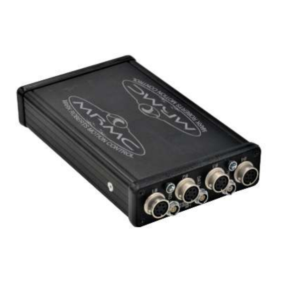
Quad Box Quick Start Guide Quad Box Quick Start Guide Introduction to Quad box connections Quad box is an MRMC axis box with a Quad card inside, usually used to drive four stepper motors. The stepper motors can be of type: ... -
Page 6: Quad Box Connector Summary
Quad Box Quick Start Guide Quad box connector summary Quad box front Quad box rear: 1-4. #1 - #4 identical connectors for any stepper motors, such as PAN and TILT in the head, track motors, and external Lens Control Motors. For pin-out information see Stepper motor connector on page POWER 18-36V connector, for power input for the head. - Page 7 Quad Box Quick Start Guide TRIGGER connector, for a bi-directional trigger signal between the head and camera. When the trigger is activated the LED next to the TRIGGER connector lights Trigger up. For pin-out information see Trigger connector (trigger out and in) on page 5.
-
Page 8: Quad Box Connector Pin-Out Information
Quad Box Quick Start Guide Quad box connector pin-out information Stepper motor connector The Quad box has four connectors for stepper motors, typically used for Pan and Tilt plus two for auxiliary devices such as a track motor or Lens Control Motor (LCM). -
Page 9: Trigger Connector (Trigger Out And In)
IP addresses which will need to be handled before this is possible. The additional Quad box will need to have an Ethernet cable connected to the Ethernet hub of the Flair system, and be powered. - Page 10 Connection tab. In the pop-up, click on the Find button. In the Find results, find the IP address of the Quad box (192.168.1.236 in this example – this is normally written on the box at the factory), and copy it into the node that you assigned to the Quad (Node 3 in this example): In the Network Setup pop-up, click on the buttons Save and Apply.
-
Page 11: Troubleshooting Finding Boards In Flair
Quad Box Quick Start Guide Click Load and exit the Network Setup. If the IP address is correct and does not conflict with any other IP on the system, and you have put the correct software name in Flair.ini then clicking on the Load button will load the board. On the... -
Page 12: Changing Ip Addresses
Flair. Example, you have just added a node to be node 3 as a Quad box, but you have no axis assigned to Network Node 3 in the Flair Screen. You will need to assign your axes to that node for them to work. - Page 13 Quad Box Quick Start Guide Once you have added the board to Flair you may still need to set up the axes. Refer to Flair manual for further details or the video “Flair Axis Setup” in the Tutorial Videos section of Resources on www.mrmoco.com.
- Page 14 Quad Box Quick Start Guide Notes...
-
Page 15: Appendix 1 Connecting Stepper Motors To Quad Box
Stepper drive pulse/direction The signal input of Step and Direction from the Quad box can be used for interfacing the pulse/direction input clock type. Note that the CW/CCW clock type is not supported by the Quad box. -
Page 16: Step/Direction Inputs
It is possible to use higher voltage as long as the current is kept within the limit, but it is highly recommend to use 5V output from MRMC Quad board (pin3). Absolute maximum is 24V, and should never be exceeded. - Page 17 Quad Box Quick Start Guide There is no enable line, therefore the enable input on the driver needs to be wired permanently enabled.
- Page 18 Quad Box Quick Start Guide Notes...
- Page 19 Quad Box Quick Start Guide Notes...
- Page 20 Mark Roberts Motion Control Ltd. Unit 3, South East Studios, Blindley Heath, Surrey RH7 6JP United Kingdom Telephone: +44 (0) 1342 838000 info@mrmoco.com www.mrmoco.com...
Need help?
Do you have a question about the QUAD BOX and is the answer not in the manual?
Questions and answers