
Related Manuals for Velocity Mega-Stor II

Summary of Contents for Velocity Mega-Stor II
- Page 1 Mega-Stor ® Stainless Steel, Buffer Tanks INSTALLATION AND OPERATING INSTRUCTIONS VELOCIT Velocity Boiler Works, LLC P.O. Box 14818 3633 I Street Philadelphia, PA 19134 www.velocityboilerworks.com 980109 - 3/19...
- Page 3 IMPORTANT INFORMATION - READ CAREFULLY NOTE: The equipment shall be installed in accordance with those installation regulations enforced in the area where the installation is to be made. These regulations shall be carefully followed in all cases. Authorities having jurisdiction shall be consulted before installations are made.
-
Page 4: Table Of Contents
CONTENTS Product Description ........3 II. Specifications ........3 III. -
Page 5: Product Description
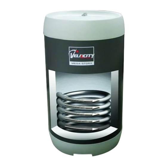
This buffer tank is for use in low pressure hydronic systems only: • Do not use in potable water systems. • Do not operate above the temperature and pressure ratings shown on the rating plate. II. SPECIFICATIONS MSB030 THRU MSB075 FIGURE 2.1: MEGA-STOR II BUFFER TANK... -
Page 6: Before Starting Installation
TABLE 2.2: PHYSICAL SPECIFICATIONS Dimensions in Inches Weight Volume Model (Gal.) Net Full MSB030 31.4 33-1/8 20-7/8 16-1/8 11-1/4 6-1/8 MSB050 52.6 49-3/4 37-5/8 24-1/2 11-1/4 6-1/8 MSB075 76.3 68-3/4 56-1/2 33-7/8 11-1/4 6-1/8 TABLE 2.3: CONNECTION SIZE (in. NPT) Model Description MSB030 - MSB075... -
Page 7: Buffer Tank Application
IV. BUFFER TANK APPLICATION A) SIZING Buffer tanks are sized using the following equation: Where: V = Required total volume (in Gallons) for the buffer tank, boiler, boiler loop piping, and any system loop piping that will always have water flowing through it regardless of what zone is calling (using V as the required buffer tank volume will yield more conservative results). Qb = Boiler output (BTU/hr). For modulating boilers use the low fire output. Qs = Smallest system heating load (BTU/hr) t = Minimum acceptable burner on time (minutes). Ten minutes is the minimum recommended value for t. ΔTD = Operating control’s differential (i.e. the difference between the temperature at which the operating control turns off the burner and the temperature at which the burner will come back on). Example: A condensing boiler having an output of 150MBH with 5:1 turndown is to be used. The differential on this particular boiler is defined in terms of a 10F “differential above” (temperature above set-point at which the burner shuts off) and a 5F “differential below” (temperature below set-point at which the burner comes on). The smallest heating zone on the system is 5000 BTU/hr. We want the burner to run for at least 10 minutes any time it fires. The volume of the boiler is 1 gallon, the boiler loop piping contains 5 gallons, and there is 6 gallons in the system piping that is common to all zones. Solution: Min Output = 150MBH ÷ 5 = 30MBH = 30000 BTU/hr Run Time = 10 minutes ΔTD = 10F + 5F = 15F ... -
Page 8: Locating The Buffer Tank
Predicting Temperature Supplied to the Heating System - The temperature of water supplied to the heating system is dependent upon the boiler supply temperature, the system load, and the relative flow rates through the boiler and system loops. The following rules of thumb can be used to estimate the system supply temperature: • Boiler Loop Flow Greater Than or Equal to System Loop Flow – System supply temperature is equal to boiler supply temperature • Boiler Loop Flow Less Than System Loop Flow – The following equation predicts system temperatures: ... -
Page 9: Piping
VI. PIPING This manual shows three alternative “four pipe” buffer tank systems. Regardless of the method used, observe the following general requirements: • Following any special requirements that the boiler manufacturer has for maximum boiler loop length, pipe size, or boiler pump selection. • Figures 6.1 to 6.3 do not necessarily show all features that may be required by the boiler manufacturer and/or applicable codes. • Note that the use of a buffer tank may require a larger size expansion tank than would otherwise be needed. • At least one automatic air vent is required in the system. In some cases, such as the piping system shown in Figure 6.1 this is the only automatic air vent that is required (although additional manual vents may be needed to adequately purge the system during initial fill). In cases where water is not always circulating though the buffer tank, a second automatic air vent and air separator is recommended in the common boiler loop piping. Method #1: No indirect water heater used - Figure 6.1 shows recommended piping when there is no indirect water heater in the system. -
Page 12: Wiring
1) As previously noted, the control well in the buffer tank is usually the best place to regulate heating system temperature. This well will accept a 3/8” sensor or capillary bulb equipped control. 2) For Velocity Phantom, Phantom X, and Raptor condensing boilers, the following sensor may be used: P/N 103104-01 (Honeywell 32003971-003) Wire this to the header sensor terminals on the boiler and follow the instructions in the boiler manual to use this sensor for CH temperature regulation.
Need help?
Do you have a question about the Mega-Stor II and is the answer not in the manual?
Questions and answers