Table of Contents
Advertisement
Quick Links
Hoffman
Installation & Operating
Instructions
General
CAUTION
�
Failure to read and understand the accompa-
nying instructions and diagrams or failure to
complete the "Checkout Procedure" prior to
energizing the Control may result in permanent
damage to the Control.
The 816-10DH Controller requires the installation of an addi-
tional line voltage to 24VAC transformer (
VAC transformer (
V
additional transformer's primary wires must be connected to the
exact same contactor terminals that supply power to the condenser
fan motor(s). Refer to Figures 3 & 4.
Pre-Installation Information /
Instruction
1. For use with Single Phase, direct drive, open frame permanent
split capacitor, or shaded pole motors. Motors are to be select-
ed or designed for variable speed drive applications.
2. Line Voltage Range: 115 VAC, 208-230 VAC, 460
600 VAC.
3. Wiring must comply with Local and National Electrical
Codes.
4. One Controller may control more than one motor.
a. Maximum running amps, under all conditions, not to
exceed 10 amps.
b. Locked Rotor Amps (LRA) not to exceed 30 Amps for 1
second.
5. Do not mount the Controller in an airtight cabinet or
compartment.
6. Application Limitation: Speed regulation and performance
characteristics will vary with motor design and motor ventilating
capability. Motors used should be designed for variable speed
operation and should be evaluated for suitability and acceptabil-
ity. TEC (totally enclosed types) are not recommended or not
generally suitable.
Installation
•
Select the appropriate line voltage wiring diagram for either a
single capacitor (Figure 3) or dual capacitor (Figure 4) configu-
ration.
•
Disconnect all factory wiring connecting the motor to the line.
|
Controls
10VA minimum). This
must
must be connected to the
V
VAC, 208-230 VAC, 460
V
VAC, or
VAC, or
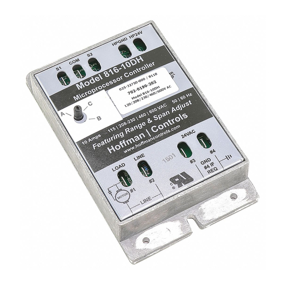
816-10DH Microprocessor Based
Electronic Head Pressure Control
•
Install the controller in a weatherproof control panel or
use HCC's NEMA 3R Weatherproof Kit (Part Number
545-0202-007). Note: Controller must be protected from
moisture and condensation.
Disconnect power from the unit and electrically
disable the compressor prior to installation.
•
Setting Minimum Speed Adjust: An adjustment, Min Speed,
is provided to accommodate the slowest allowable speed for ball
bearing or sleeve bearing type motors.
Recommended Minimum Speed
Ball Bearing Motors
Sleeve Bearing Motors
• Do not install the Controller in an airtight compart-
ment, or near heat generating sources.
• Do not attempt to set Minimum Speed Adjust to obtain
a desired head pressure. This adjustment is only provided
to compensate for fan bearing type and must not be used
otherwise. Improper operation will result.
• Single sensor application must use the control's "S1" &
"COM" terminals. (Motor will run at full speed if sensor
is not connected to "S1" & "COM").
Heat Pump Mode Jumper
Heat Pump Applications
For Heat Pump System applications, the lower "H P" jumper tab
position is as follows: (See Figure 1)
Jumper position "RA" is used when the Heat Pump reversing
(changeover) valve is activated (Heat Mode) by the absence of 24
VAC at the Heat Pump input terminals of the Control.
Jumper position "DA" is used when the Heat Pump reversing
(changeover) valve is activated (Heat Mode) by the presence of 24
VAC at the Heat Pump input terminals of the Control.
Note: The Condenser Fan Motor should run at full speed when in the
heating mode. The applicable RA or DA method of operation varies by
manufacturer and must be verified by the Installer/Service Technician.
1
WARNING
200 RPM
7–9 o'clock
400 RPM
3–5 o'clock
IMPORTANT
presence of 24
�
�
Advertisement
Table of Contents

Related Manuals for Hoffman Controls 816-10DH

Summary of Contents for Hoffman Controls 816-10DH
- Page 1 Disconnect power from the unit and electrically energizing the Control may result in permanent disable the compressor prior to installation. damage to the Control. The 816-10DH Controller requires the installation of an addi- • Setting Minimum Speed Adjust: An adjustment, Min Speed, 10VA minimum). This...
- Page 2 Heat Pump applications, the condenser fan motor will operate at Checkout Procedure full speed and will not modulate. 816-10DH Span Step 1 A selectable span of 25ºF or 30ºF is available (see Figure 1). With power disconnected and the Controller wired: The 25ºF span is recommended for high efficiency units while the...
- Page 3 � ������� � �� � ������ ��������� �� ������� �� ��� ����� ����� ������� ��� ���������� ���� ���� �� ��������� �� �������� �� ����� Wiring Diagram for the 816-10DH Figure 3 �� ���� ������� ���� ��������� �� �� ������� �...
- Page 4 Checkout Procedure Con't Temp Sensor Temp Sensor Temp Sensor ºF (Ohms) ºF (Ohms) ºF (Ohms) Above Selected Span and Range, The motor(s) will start 40.0 40.0 40.0 26,109 26,109 26,109 64.0 64.0 64.0 13,823 13,823 13,823 88.0 88.0 88.0 7,685 7,685 7,685 and remain at full speed when temperatures are above the...
Need help?
Do you have a question about the 816-10DH and is the answer not in the manual?
Questions and answers