Table of Contents

Advertisement

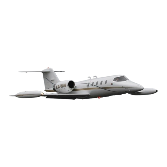
Gates Learjet 35A/36A
with
FC-200 Autopilot
FAA APPROVED AIRPLANE FLIGHT MANUAL
THIS AIRPLANE MUST BE OPERATED IN COMPLIANCE WITH THE
PRESCRIBED LIMITATIONS IN SECTION 1 OF THIS MANUAL
___________________ NOTICE __________________ _
This AFM
is
a revised issue of the original AFM dated 4-30-76. This
reissue replaces all of the information in the original issue through
Change 13.
FM-102
SERIAL NO. _ _ _ _ _ _ _
N ______________ __
for CHIEF, AIRCRAFT CERTIFICATION PROGRAM
FAA CENTRAL REGION
WlCHIT A, KANSAS
Copyright
©
1983
GATES LEARJET CORPORATION
All rights reserved

Advertisement

Table of Contents
loading

Summary of Contents for Learjet 35A

  • Page 2 TECHNICAL PUBLICATIONS USER COMMENT SHEET The Bombardier-Learjet Technical Publications Team is continually striving to make our publications more usable to those in the field. We welcome your comments, criticism, and suggestions concerning any Bombardier-Learjet publication. The action taken, as the result of your comments, will be noted below and a copy returned to you.
  • Page 5 LOG OF TEMPORARY FLIGHT MANUAL CHANGES This list is intended to assist the flight crew in determining the applica- ble AFM temporary flight manual changes for Model 35A/36A aircraft equipped with FC-200 autopilot. It is the responsibility of the aircraft owner and operator to maintain their basic AFM with the temporary changes applicable to their aircraft.
  • Page 6 Temporary Changes Learjet 35A/36A with FC-200 TFM # Section Dated or Page Description Status 84-02 Maximum zero wing and tip fuel weight Removed by 3-15-84 replaces maximum wing bending weight. Chg 5. 85-02 Removed by Revised FUEL CMPTR light procedure.
  • Page 7 Learjet 35A/36A with FC-200 Temporary Changes TFM # Section Dated or Page Description Status 2001-15 Revises Single Engine Landing Removed by 4-44 4-13-01 procedure. Chg 13. 2007-02 Revises Stall Warning Activates proce- Removed by 3-46 6-14-07 dure. Chg 14. 2007-04...
  • Page 8 Use this List of Effective Pages to determine the current status of the Airplane Flight Manual. Pages affected by the current change are indicated by an asterisk (*) immediately preceding the page number. Learjet 35A/36A with FC-200 Autopilot AFM Dates of issue for Original and Changed pages are: Original..O ..4-30-1976 Change..
  • Page 9 List of Effective Pages Learjet 35/36 AFM LIST OF EFFECTIVE PAGES (Cont) Learjet 35A/36A with FC-200 Autopilot AFM Page Change Page Change Normal Procedures 3-31 and 3-32....... 13 II-1 and II-2 ......12 3-33 thru 3-36 ...... 10 II-3 ........10 3-37 ........
  • Page 10 Learjet 35/36 AFM List of Effective Pages LIST OF EFFECTIVE PAGES (Cont) Learjet 35A/36A with FC-200 Autopilot AFM Page Change Page Change Performance Data 5-37 ........9 V-1 ........10 5-37A........9 V-2 ........12 5-37B and 5-37C ....12 V-3 ........
  • Page 16: Table Of Contents

    SECTION I — LIMITATIONS TABLE OF CONTENTS General Certification Status..............1-1 Type of Operation ..............1-1 Performance Configuration ............1-1 Minimum Flight Crew..............1-1 Maneuvers ................1-1 Weight and C.G. Limits Maximum Ramp Weight ............1-2 Maximum Certified Takeoff Weight..........1-3 Maximum Zero Wing and Tip Fuel Weight ........1-3 Maximum Allowable Takeoff Weight...........1-4 Maximum Certified Landing Weight..........1-4 Maximum Allowable Landing Weight ..........1-5...
  • Page 17 TABLE OF CONTENTS (Cont) Takeoff and Landing Operational Limits Temperature Limits..............1-13 Maximum Altitude ..............1-13 Wind Components..............1-13 Runway Conditions..............1-13 Maximum Nose Wheel Steering Speed ........1-13 Tire Limiting Speed ..............1-13 Tip Tank Fuel.................1-13 Minimum Fuel ................1-13 Pressurization.................1-14 Seat Belts ................1-14 Enroute Operational Limits Temperature Limits..............1-14 Maximum Operating Altitude...........1-14 Flight Load Acceleration Limits..........1-14...
  • Page 19: General

    GENERAL CERTIFICATION STATUS This airplane is certified in accordance with FAR 25. TYPE OF OPERATION This aircraft is approved for VFR, IFR, day, night, and icing conditions. When icing or frost conditions exist, this airplane must be inspected and operated in accordance with the Cold Weather Operation procedures of Section II.
  • Page 20: Weight And C.g. Limits

    NOTE Ramp Weight shall not exceed Maximum Allowable Takeoff Weight by more than 250 lbs (113 kg). MODEL 35A: • Serials 35-067 and subsequent not incorporating ECR 1495, ECR 2234, AAK 77-8, or AAK 80-2 ..17,250 Pounds 7,825 kg •...
  • Page 27: Airspeed/Mach Limits

    AIRSPEED/MACH LIMITS All Airspeed/Mach Limits are expressed in terms of in- NOTE dicated values unless otherwise stated. Instrument error is assumed to be zero. MAXIMUM OPERATING SPEED V MO /M MO Do not extend spoilers, or operate with spoilers WARNING deployed, at speeds above V MO /M MO due to signifi- cant nose-down pitching moment associated with spoil- er deployment.
  • Page 39: Pressurization Limit

    SYSTEM LIMITS (CONT) PRESSURIZATION LIMIT Maximum Differential Pressure..........10.0 PSI WINDSHIELD AND RADOME ANTI-ICE FLUID Methyl Alcohol (Methanol) per Federal Specification O-M-232, Grade A, is required. THRUST REVERSERS (IF INSTALLED) When thrust reversers are installed, refer to the applicable Thrust Reverser Supplement for limitations, normal procedures, emergency procedures, ab- normal procedures, and performance data.
  • Page 40: Powerplant Limits Engine Speed Limits

    POWERPLANT LIMITS ENGINE SPEED LIMITS CONDITION LIMIT OVERSPEED 105% N or N TRANSIENT 5 SECONDS 103-105% N or N 1 MINUTE 100-103% N or N TAKEOFF Refer to TAKEOFF POWER SETTING charts in Section V. MAXIMUM Refer to MAXIMUM CONTINUOUS THRUST CONTINUOUS tables in Section V.
  • Page 41 TURBINE TEMPERATURE LIMITS (ITT) STARTING TIME-SECONDS F31-011500-000-01 Abort start. Record maximum ITT and time in excess of 860°C in engine log book. Determine cause and correct prior to next start. Abort start. Record maximum ITT and time in excess of 860°C in engine log book.
  • Page 42 TURBINE TEMPERATURE LIMITS (ITT) EXCEPT STARTING 832°C TIME-SECONDS TIME-MINUTES F31-011500-000-02 Takeoff Transient Limit. Reduce thrust setting to within limits and make electronic computer N adjustment before next flight. Record maximum ITT and time in excess of limit in engine log book. Observe takeoff ITT limit.
  • Page 43: Fuel Temperature

    FUEL LIMITS FUEL TEMPERATURE Do not take off with fuels other than JP-4 or equivalent at fuel tempera- tures below -29°C (-20°F). Do not take off with fuel temperature lower than -54°C (-65°F). UNUSABLE FUEL The fuel remaining in the fuel tanks when the fuel quantity indicator reads zero is not usable in flight.
  • Page 50: Turbine Speed (N2)

    INSTRUMENT MARKINGS (CONT) TURBINE SPEED (N Green Arc ........ 48%-100% Yellow Arc ...100%-103% (One minute limit) Red Line ......... 103% TURBINE TEMPERATURE (ITT) Green Arc ......230°C-832°C Yellow Arc ......832°C-860°C Red Line ........860°C (Refer to Figure 1-5 and Figure 1-6) FAA APPROVED 4-30-76 1-27 REISSUED 2-25-81, CHANGE 13...
  • Page 51 INSTRUMENT MARKINGS (CONT) FAN SPEED (N Green Arc ....... 24%-100% Yellow Arc..100%-103% (One minute limit) Red Line ......... 103% OIL PRESSURE Red Line (Min.) ....... 25 PSI Yellow Arc......... 25-38 PSI Green Arc ......... 38-46 PSI Yellow Arc......... 46-55 PSI Red Line (Max.) ......
  • Page 56 TABLE OF CONTENTS (Cont) Emergency Lighting System (If Installed) Aircraft 35-067 thru 35-415 and Aircraft 36-018 thru 36-047 ..........2-82 Aircraft 35-416 & Subsequent and Aircraft 36-048 & Subsequent ..........2-83 Annunciator Panel ..............2-84 Engine Synchronizer ..............2-85 FAA APPROVED 4-30-76 II-3 REISSUED 2-25-81, CHANGE 10...
  • Page 57 INTRODUCTION TO NORMAL PROCEDURES The procedures in this section of the manual have been developed by Learjet Inc. for certification of this aircraft. This section contains those procedures which may be considered routine in day-to-day operations. The presentation includes, but is not limited to, detailed checklist procedures by flight phase.
  • Page 66: Before Starting Engines

    BEFORE STARTING ENGINES (CONT) PITCH TRIM Switch — PRI. JET PUMP Switches — ON. EMER PRESS Switches (if installed) — NORMAL except for takeoff above 8500 feet pressure altitude. Aircraft with emergency pressurization override NOTE switches installed. For takeoff at field elevations above 8500 feet pressure altitude, refer to PRESSURIZA- TION SYSTEM OPERATION, this section.
  • Page 67 BEFORE STARTING ENGINES (CONT) Auxiliary Inverter (if installed) — Check: (1) AUX INVERTER ON-OFF Switch — ON. Check AUX INV light not illuminated. (2) SEC INVERTER Switch — OFF. Check AC VOLTS read- ing is within green arc. PRI, SEC, and AUX INVERTER (if installed) Switches — On. On aircraft with auxiliary inverter, it is recommended NOTE that all three inverters be On during normal operations...
  • Page 68 BEFORE STARTING ENGINES (CONT) (2) TEST Button — Depress. FIRE PULL or ENG FIRE PULL T-Handle shall illuminate and flash. This indicates continu- ity of the fire detect systems. (3) TEST Button — Release. It is recommended that one engine be started after NOTE Step c if external power is not being used.
  • Page 69 BEFORE STARTING ENGINES (CONT) (a) As the needle passes the green-yellow margin, the shaker will actuate and the L STALL warning light shall flash. (b) As the needle advances to the red segment, the pusher will actuate briefly, then stop. L STALL warning light will illuminate steady just prior to or at pusher actua- tion.
  • Page 70 BEFORE STARTING ENGINES (CONT) (5) Cabin RATE Selector — Position as desired. (6) IN NORMAL-OUT DEFOG Knob — Push in. • Aircraft 35-107, 35-113 and subsequent and 36-032 and subsequent. (1) L and R BLEED AIR Switches — Check, On. (2) CAB AIR Switch —...
  • Page 71 BEFORE STARTING ENGINES (CONT) Actuate pilot’s and copilot’s control wheel trim and trim arm- ing switches and pedestal NOSE DN-OFF-NOSE UP switch. Trim motion shall not occur. PITCH TRIM Switch —þPRI. Pedestal NOSE DN-OFF-NOSE UP Switch — Operate NOSE UP, then NOSE DN. Trim motion shall not occur. Pilot’s Control Wheel Trim Switch —...
  • Page 72 BEFORE STARTING ENGINES (CONT) Attitude Director Indicator (ADI) flags and Horizontal Situation Indicator (HSI) flags — Check that flags have disappeared. This indicates that vertical and directional gyros have been ener- gized long enough to time-out erection cycles (approx. 90 sec- onds).
  • Page 73 BEFORE STARTING ENGINES (CONT) Control Wheel — Rotate to full left, rudder pedals will deflect to the left. Rotate to full right, rudder pedals will deflect to the right. SEC ENG OFF Button — Depress. SEC ENG light will extin- guish and yaw damper will disengage.
  • Page 74: Takeoff Trim. Cg Function (Figure 2-2)

    TAKEOFF TRIM • CG FUNCTION Aircraft 35-146 & subsequent, aircraft 36-036 & subsequent, and prior aircraft incorporating AAK 83-8 Figure 2-2 FAA APPROVED 4-30-76 2-17 REISSUED 2-25-81, CHANGE 10...
  • Page 75: Starting Engines

    CAUTION do not dispatch if red BAT 140 or BAT 160 warning light comes on at any time prior to takeoff, including en- gine start. Check batteries per Learjet Maintenance Manual. 1. Cabin Door — Closed and locked. Both Door Handles — Forward.
  • Page 112: Oxygen System

    OXYGEN SYSTEM (CONT) To obtain 100% oxygen at any time, depress 100% lever on mask pressure regulator. For emergency operation, select EMERGENCY (rotate PRESS TO TEST button/knob to G). With the mask pressure regula- tor controls in this position the crew mask will deliver 100% oxygen at all cabin altitudes and maintain a positive pressure in the mask cup at all times for respiratory protection from smoke or fumes.
  • Page 113: Emergency Braking

    BRAKE SYSTEMS (CONT) Anti-skid Off Operation: When anti-skid is inoperative, care must be used during brake application and stopping distances will be increased. Refer to Section IV for operation of the brake system with anti-skid off, and Section V for increased stopping distances.
  • Page 143 SECTION III — EMERGENCY PROCEDURES TABLE OF CONTENTS Electrical Complete AC Power Failure — Loss of all Inverters ......3-1 Battery Overheat .................3-2 Current Limiter Failure/Illumination of CUR LIM (CUR LIMITER) Light in Flight ........3-3 DC Power Loss — Essential Bus Aircraft 35-067 thru 35-201, 35-205, and Aircraft 36-018 thru 36-040 except when these Aircraft Incorporate AMK 78-13 ...........3-4...
  • Page 144 TABLE OF CONTENTS (Cont) Overspeed Recovery — Overspeed Warning Horn Activates ..3-37 Pitch Axis Malfunction ...............3-38 Roll or Yaw Axis Malfunction ............3-41 Fuel FUEL PRESS Light Illuminated ...........3-42 Landings Ditching..................3-43 Emergency Braking ..............3-45 Emergency Evacuation ...............3-45 Landing — Both Engines Inoperative ..........3-46 Stall Warning Activates ............3-47 Takeoff Aborted Takeoff ................3-48...
  • Page 152: Dc Power Loss - Essential Bus

    DC POWER LOSS — ESSENTIAL BUS (Aircraft 35-202 thru 35-204, 35-206 & subsequent, aircraft 36-041 & subsequent, and prior aircraft incorporating AMK 78-13) (CONT) 4. Restrict operation of the following systems to one at a time. Pitch, roll and yaw trims. Fuel transfer and standby pumps.
  • Page 153: Dual Generator Failure

    DUAL GENERATOR FAILURE 1. Electrical Load — Reduce. COOL-FAN Switch — OFF. AUX HT Switch (if installed) — OFF. On aircraft incorporating AAK 86-1 or SB 35/36-21-17, W/S AUX HEAT DEFOG Switch — OFF. 2. L and R IGN & ST Circuit Breakers (main power bus) — Check and reset.
  • Page 176: Cabin/Cockpit Fire, Smoke, Or Fumes

    CABIN/COCKPIT FIRE, SMOKE, OR FUMES 1. Crew Oxygen Masks — Don. Select 100% oxygen. 2. Smoke Goggles — Don, if available. 3. Pilot and Copilot OXY-MIC Switches — ON. It may be necessary to select EMER or EMERGENCY NOTE on 6600214 series or Scott ATO mask regulator if the mask does not seal properly.
  • Page 177 CABIN/COCKPIT FIRE, SMOKE, OR FUMES (CONT) If time and conditions permit: 10. Isolate source of smoke or fumes. • If Bleed Air System is suspected source: R BLEED AIR Switch — OFF. If smoke is reduced, continue operation with switch OFF. If smoke is not reduced, R BLEED AIR Switch —...
  • Page 184 PITCH AXIS MALFUNCTION (CONT) 4. STALL WARNING Switches — OFF. 5. PITCH TRIM Switch (pedestal) — OFF. 6. AUTOPILOT Switch — OFF. 7. Control Wheel Master Switch (MSW) — Release. 8. Yaw Damper (PRI or SEC) — Engage. If flight conditions permit, isolate malfunction as follows: 9.
  • Page 185 PITCH AXIS MALFUNCTION (CONT) 10. Stall Warning System: STALL WARNING Switches — ON, one at a time, to isolate malfunctioning system. If malfunction recurs, set appropriate switch OFF. • An abrupt nose-down control column movement is NOTE evidence of a stick pusher malfunction. •...
  • Page 190: Emergency Braking

    EMERGENCY BRAKING In the event of failure of the normal brake system, emergency brakes can be used to stop the airplane. When using emergency braking, anti-skid pro- tection is not available, and the anti-skid OFF corrections presented in Sec- tion V will be applicable. 1.
  • Page 191: Landing - Both Engines Inoperative

    LANDING — BOTH ENGINES INOPERATIVE Airplane best glide speed, in the clean configuration, is V + 60. The still-air gliding distance is approximately 2 nm per 1000 feet of altitude. 1. If time permits: Transponder — Emergency 7700. Advise controlling agency. Prepare passengers for emergency landing.
  • Page 192: Stall Warning Activates

    STALL WARNING ACTIVATES The stall warning computer has sensed a limit angle of attack. The red STALL lights will flash, the control column stick shaker will activate, and the angle-of-attack indicators will be in the yellow segment. If the angle of attack continues to increase, the stick pusher will activate.
  • Page 193 ABORTED TAKEOFF 1. Thrust Levers — IDLE. 2. Wheel Brakes — Apply. 3. Spoilers — EXT. 4. Drag Chute or Thrust Reversers (if installed) — Deploy, if necessary. 5. • If rejected takeoff was made at a speed of less than 40 knots, one subsequent takeoff attempt may be made without any waiting period.
  • Page 194 SECTION IV — ABNORMAL PROCEDURES TABLE OF CONTENTS Anti-Icing ALC AI Light Illuminated ..............4-1 Engine Ice Ingestion ..............4-1 ENG ICE Light Illuminated............4-2 Inadvertent Icing Encounter ............4-3 Pitot Heat Light Illuminated (if installed) .........4-4 Stabilizer Heat Failure ..............4-4 STAB OV HT Light Illuminated.............4-5 Wing Heat Failure ................4-6 WING OV HT Light Illuminated ............4-7 Windshield Heat Failure..............4-7...
  • Page 195 TABLE OF CONTENTS (Cont) Cabin Altitude Exceeds 8500 Feet — Aircraft 35-067 thru 35-112 except 35-107 and Aircraft 36-018 thru 36-031..4-18 CAB ALT Light Illuminated or Cabin Altitude Exceeds 8500 Feet — Aircraft 35-107, 35-113 & Subsequent and Aircraft 36-032 & Subsequent ........4-19 Oxygen Duration Aircraft with ZMR 100 Series Crew Masks (Figure 4-1)....4-22 Aircraft with 6600214 Series Crew Masks (Figure 4-2) ....4-23...
  • Page 196 TABLE OF CONTENTS (Cont) Instruments/Avionics Pitot-Static System Malfunction...........4-37 Vertical Gyro Monitor Light Illuminated ........4-38 Landing Gear Alternate Gear Extension/Electrical Malfunction......4-39 Alternate Gear Extension/Hyd Malfunction..(See Hydraulic System) ANTI-SKID GEN Light Illuminated — Anti-Skid Off Operation ..4-39 Nose Wheel Steering Malfunction ..........4-40 Landings Gear Up Landing...............4-40 Hydraulic System Failure Landing ..........4-42...
  • Page 197 INTRODUCTION TO ABNORMAL PROCEDURES The procedures in this section of the manual have been developed by Learjet Inc. for certification of this aircraft. This section contains those op- erating procedures requiring the use of special systems and/or alternate use of regular systems which, if followed, will maintain an acceptable level of airworthiness or reduce operational risk resulting from a failure condition.
  • Page 206: Single Generator Failure

    SINGLE GENERATOR FAILURE 1. Electrical Load — Reduce. COOL-FAN-OFF Switch — OFF. Shed other loads as required to observe generator limits. 2. IGN & ST Circuit Breaker (main power bus) — Check and reset. 3. START-GEN Switch — GEN. NOTE START-GEN switch must be set to GEN for GEN RESET switch to be effective.
  • Page 207: Inverter Failure - Partial Ac Power Loss

    INVERTER FAILURE — PARTIAL AC POWER LOSS An inverter system failure is indicated by illumination of the PRI INV, SEC INV, and/or AUX INV (if installed) lights. An INV light will illuminate when- ever the associated inverter is on and voltage and/or current flow on the corresponding AC bus falls below a minimum value.
  • Page 208: Abnormal Engine Operation

    INVERTER FAILURE — PARTIAL AC POWER LOSS (CONT) If auxiliary inverter system malfunctions: AUX AC BUS Circuit Breaker (ac bus) associated with failed AC bus — Pull. AUX INVERTER Bus Switch — Select opposite AC bus. AUX INV Circuit Breaker (copilot’s ess bus) — Check and reset.
  • Page 209: Eng Chip Light Illuminated

    FUEL CMPTR LIGHT ILLUMINATED (CONT) Affected Engine: 1. FUEL COMPTR Circuit Breaker (ess bus) — Check and reset if necessary. 2. FUEL CMPTR Switch — Cycle once. If fuel computer does not come back on line, FUEL CMPTR Switch — OFF. Fan Speed (N ) must be 50% to 60% when switching NOTE...

This manual is also suitable for:

36a

Table of Contents