Table of Contents
Advertisement
Quick Links
Advertisement
Table of Contents

Summary of Contents for Norsat LNB
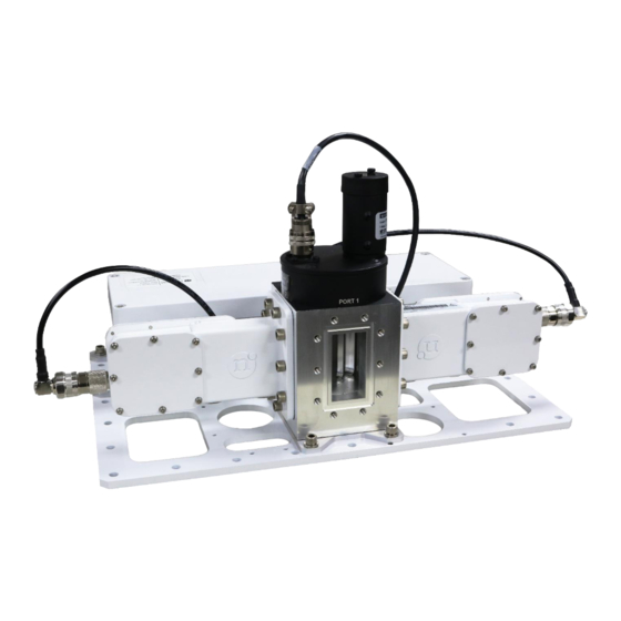
- Page 1 USER MANUAL LNB 1:1 Redundant Switch ODU FW Version: 1.0.0 IDU FW Version: 1.0.0...
-
Page 2: Table Of Contents
TABLE OF CONTENTS TABLE OF CONTENTS ......................2 Acronyms ........................... 3 Safety ............................4 LNB 1:1 Redundant Switch System Overview ..............5 Operation ........................5 System ......................... 5 Getting Started ........................6 Warnings ........................6 ODU Setup ........................6 ODU IFL installation ....................16 IDU installation (Optional) ...................17... -
Page 3: Acronyms
Acronyms Alternating Current Control Interface Indoor Unit Interfacility Link Low-noise Block Downconverter Radio Frequency SNMP Simple Network Management Protocol Universal LNB Controller © Norsat International Inc. (“Norsat”) All Rights Reserved 2021-12-20 DOC-001527 Rev A... -
Page 4: Safety
Use of non-approved accessories or devices may lead to a degradation in performance, damage to equipment, or potential hazards. Warning AC Power This device uses AC power. Proper grounding of equipment is necessary for safety purposes. © Norsat International Inc. (“Norsat”) All Rights Reserved 2021-12-20 DOC-001527 Rev A... -
Page 5: Lnb 1:1 Redundant Switch System Overview
The LNB 1:1 Redundant Switch system (RSW) provides LNB redundancy by automatically switching to a backup LNB in the event of an LNB failure. During normal operation, there is one Active LNB and one Standby LNB which are both monitored continuously. LNB health monitoring is accomplished by watching the LNB active power consumption. -
Page 6: Getting Started
Inspect all cables for damage prior to connecting them to the system. 2.2 ODU Setup 2.2.1 Ku/Ka-Band LNB Installation LNB installation for Ku-band and Ka-band components are identical, except different sized fasteners are provided. The following components are included with the LNB mounting kit. - Page 7 (Interfaces for Rx In 2, IF Out 3 and LNB 3 are only present in 2:1 redundant switches) IF Out 1 LNB 1 IF Out LNB 2 IF Out 3 Rx In LNB 3 Rx In Repeat the following steps for each LNB interface: 1.
- Page 8 3. On the thread of Item 1, apply two to three drops of Item 3. Repeat this step for four times. Item 3 Item 1 4. Install the LNB onto the Rx In of redundant switch using the Item 1from step 3 above and one Item 2 on each Item 1 with Tool 1. Item 2 Item 1 5.
- Page 9 2.2.2 C-Band LNB Installation The following components are included with the LNB mounting kit. Item 1 (Socket Cap Screw) Item 2 (Washer) Item 3 (Threadlocker) Item 4 (Gasket) Item 5 (Adaptor Plate) Item 6 (Set Screw) Item 7 (Nut) The following tools are required (not included with the mounting kit).
- Page 10 IF Out 1 IF Out 2 LNB 1 Rx In LNB 2 © Norsat International Inc. (“Norsat”) All Rights Reserved 2021-12-20 DOC-001527 Rev A...
- Page 11 Complete this step for three Item 6. Item 3 Item 6 Socket Head 3. Fasten Item 6 from step 2 above into the LNB interface using Tool 2. Item 6 © Norsat International Inc. (“Norsat”) All Rights Reserved 2021-12-20 DOC-001527 Rev A...
- Page 12 4. Insert Item 4 into the LNB interface on the redundant switch and align Item 5 onto Item 6 installed from step 3 above. Item 4 Item 5 5. Insert the gasket included with the LNB into the groove on the LNB.
- Page 13 6. On the thread of Item 1, apply two to three drops of Item 3. Complete this step for five Item 1. Item 3 Item 1 6. Install the LNB onto the Rx In of redundant switch using Item 1 fromstep 5 above and one Item 2 on each Item 1 with Tool 1. Item 2 Item 1 ©...
- Page 14 8. Tighten all surrounding screws and nuts to fasten the LNB onto the redundant switch. 9. Connect the LNB to the IF Out port with the matching number for the LNB position. (i.e. LNB 1 connects to IF OUT 1) ©...
- Page 15 Depending on the redundant switch configuration, some holes may be inaccessible. Follow these general guidelines when mounting the redundant switch: • Engage a minimum of 15 holes • Use medium strength threadlocker © Norsat International Inc. (“Norsat”) All Rights Reserved 2021-12-20 DOC-001527 Rev A...
-
Page 16: Odu Ifl Installation
4. If you have purchased the optional IDU, proceed to Section 2.4. If the RSW is being operated in the headless configuration, you can now power on the system by connecting the PWR cable to AC power. © Norsat International Inc. (“Norsat”) All Rights Reserved 2021-12-20 DOC-001527 Rev A... -
Page 17: Idu Installation (Optional)
3. Connect the Ethernet RJ-45 connector from the IFL to the ETH ODU port. 4. (Optional) Connect the Network port to any external network connection (cable not included). © Norsat International Inc. (“Norsat”) All Rights Reserved 2021-12-20 DOC-001527 Rev A... -
Page 18: Safety Ground
ODU grounding point and IDU grounding point (if applicable). The grounding point locations are shown below. ODU Grounding Point IDU Grounding Point © Norsat International Inc. (“Norsat”) All Rights Reserved 2021-12-20 DOC-001527 Rev A... -
Page 19: Odu Monitoring And Control
While the Manual Override is disabled, the RSW will run in Automatic Mode. While in Automatic Mode, the RSW automatically switches from the Active LNB to the Standby LNB if there is a fault present on the Active LNB. The table below summarizes the RSW actions based on the fault status while in Automatic Mode. -
Page 20: Lnb Power
3.3.2 Power over IF Cable If the power to the LNB is being supplied by an external source, the ULC must be set to DISABLED. In this operating mode, the Active Device is supplied with the IF power and the Standby Device is provided with 18V. -
Page 21: Default Network Settings
SNMP Trap Port 3.5 LNB Replacement In the event of an LNB failure or routine maintenance, LNBs can be installed and removed while the system is powered on. To prevent any system downtime, it is recommended to switch the Active Device so that the unit being replaced is in the standby position. - Page 22 The device Info page will show the current status of the RSW system. The Identification section will show the device configuration, serial number, firmware version, and LNB model. In the case that the LNB being used is not a Norsat LNB, the LNB Model will be set to “UNKNOWN”.
- Page 23 Unknown, fault status has not yet been initialized No Faults, the value is currently within the expected range Warning, the value has exceeded the warning threshold Fault, there is a fault present © Norsat International Inc. (“Norsat”) All Rights Reserved 2021-12-20 DOC-001527 Rev A...
- Page 24 1. Select the desired value in the applicable drop-down menu. 2. Select the Set button on the right to change the applicable setting. 3. The system controls will be temporarily disabled as the system is updated. © Norsat International Inc. (“Norsat”) All Rights Reserved 2021-12-20 DOC-001527 Rev A...
- Page 25 The Advanced Settings section displays the number of LNB bands, Upper Limit, Lower Limit, Upper Warning, and Lower Warning. To change these settings, click the “Advanced Settings” checkbox in the “Redundancy Switch Configuration” section. To update the Advanced Settings: 1. Update the setting value of interest.
- Page 26 3.6.6 Firmware Update To perform a firmware update on the RSW ODU, perform the following steps: 1. Obtain a valid RSW ODU firmware update file from Norsat. 2. Open the Web Interface in Firefox. 3. Select “Browse” and navigate to the firmware file.
-
Page 27: Snmp
Read Community String Public Write Community String Write Community String Public 3.7.2 SNMP parameters To access the RSW SNMP parameters, download the latest MIB file from Norsat. A summary of all accessible parameters is shown below: Product Configuration PARAMETER DESCRIPTION ACCESS... - Page 28 LNBs, this value will be set to 1. Device Model The model of the LNB model used. If Read-only this device is not a Norsat LNB, it shall be initialized to "UNKNOWN". Factory Reset Factory Reset. Write 1 to trigger a Read-write factory reset of the Redundant Switch.
- Page 29 Get Config Response format: MODEL <device model number> LW <lower Read-only warning> UW <upper warning> LL <lower limit> UL <upper limit> ULC <1=enabled, 0 = disabled> BANDS <number LNB bands> Get Status Response format: MO <manual override> A <active device> SB Read-only <standby device>...
-
Page 30: Odu Manual Override Switch
Do not hold the switch in the new position if the system is trying to switch back to the previous device. This may cause damage to the motor. 4. Replace the switch cover. © Norsat International Inc. (“Norsat”) All Rights Reserved 2021-12-20 DOC-001527 Rev A... -
Page 31: Factory Reset
3.9 Factory Reset Performing a factory reset on the ODU will reset all user configurable values including Network Settings, Current Limits, ULC settings, LNB bands, and SNMP settings. 3.9.1 Web Interface Factory Reset To perform a factory reset of the ODU through the web interface: 1. - Page 32 2. Open the ODU lid by unscrewing the four screws on the top of the controller box. 3. Locate the DIP switch on the circuit board shown below. © Norsat International Inc. (“Norsat”) All Rights Reserved 2021-12-20 DOC-001527 Rev A...
- Page 33 4. Toggle the position of switch 4. 5. Reinstall the controller box lid. 6. Power on the RSW. The factory reset will now occur. © Norsat International Inc. (“Norsat”) All Rights Reserved 2021-12-20 DOC-001527 Rev A...
-
Page 34: Idu Operation
Moves the indicator to the left if possible Enter If selecting a subpage, displays that subpage. If changing a setting, saves the setting and moves to the previous page. © Norsat International Inc. (“Norsat”) All Rights Reserved 2021-12-20 DOC-001527 Rev A... - Page 35 Yellow Solid Device is in a WARNING state Red Solid Device is in an ALARM state Red Flashing Slow Device ERROR Red Flashing Fast Device is NOT PRESENT © Norsat International Inc. (“Norsat”) All Rights Reserved 2021-12-20 DOC-001527 Rev A...
-
Page 36: Lcd Screen
Pressing Enter takes the user to that specific settings page. Pressing Back takes the user to the previous page. Menu flow charts are shown below: © Norsat International Inc. (“Norsat”) All Rights Reserved 2021-12-20 DOC-001527 Rev A... - Page 37 Press Enter on the indicated device to go to the Device Status page. If the IDU is unable to communicate with the ODU, the following error message will be displayed ERROR: THERE IS NO CONNECTION WITH THE ODU. © Norsat International Inc. (“Norsat”) All Rights Reserved 2021-12-20 DOC-001527 Rev A...
- Page 38 Next or Previous buttons. PARAMETER DESCRIPTION ACCESS Range Num Bands Number of LNB bands. This value is set Read-write 1 to 4 to 1 for single band LNBs. Current Band Current ULC band...
- Page 39 ODU IP address on the unit. If the user wants to change the ODU’s IP address, this must be performed through the ODU’s Web Interface (see Section 3.6.4). © Norsat International Inc. (“Norsat”) All Rights Reserved 2021-12-20 DOC-001527 Rev A...
- Page 40 Pressing Enter saves the new IP address and returns the user to the Network Settings page. Pressing Back takes the user to the Network Settings page without saving any values. © Norsat International Inc. (“Norsat”) All Rights Reserved 2021-12-20 DOC-001527 Rev A...
- Page 41 The Select Active Device Page allows the user to change which device is active. Pressing Enter updates the Active Device if allowed. Note: Pressing the Manual Override switch brings the user to this screen, allowing them to change the Active Device. © Norsat International Inc. (“Norsat”) All Rights Reserved 2021-12-20 DOC-001527 Rev A...
- Page 42 (measured in mA). Pressing Previous and Next allows the user to select which digit to change. Pressing Up and Down changes the value of the digit by 1. Pressing Enter saves the value and returns the user to the Device Settings Page. © Norsat International Inc. (“Norsat”) All Rights Reserved 2021-12-20 DOC-001527 Rev A...
- Page 43 ULC band is active. Pressing Enter saves the selection and returns the user to the Settings Page. Pressing Back takes the user to the Settings Page without saving. © Norsat International Inc. (“Norsat”) All Rights Reserved 2021-12-20 DOC-001527 Rev A...
- Page 44 The A after the IDU Software Version indicates that the software is running the normal application software. If any errors are detected in the software, it runs the Gold application software instead, indicated by a “G” after the Software Version. © Norsat International Inc. (“Norsat”) All Rights Reserved 2021-12-20 DOC-001527 Rev A...
-
Page 45: Idu Web Interface
4.3.2 IDU Identification The IDU Identification section displays the Serial Number, Device Configuration (1:1 or 2:1, BUC or LNB), and Firmware Version of the IDU. These values are not user configurable. © Norsat International Inc. (“Norsat”) All Rights Reserved 2021-12-20 DOC-001527 Rev A... - Page 46 To update the sounds settings: 1. Select the desired sound settings using the radio buttons on the right 2. Press Save Settings to implement the changes. © Norsat International Inc. (“Norsat”) All Rights Reserved 2021-12-20 DOC-001527 Rev A...
- Page 47 The Update IDU Firmware section allows the user to update the firmware on the IDU. To update the firmware: 1. Obtain a valid RSW IDU firmware update file from Norsat. 2. Open the Web Interface in Firefox. 3. Select “Browse” and navigate to the firmware file.
-
Page 48: System Troubleshooting
1. Verify that the ODU power connector is properly seated and threaded. not receiving power 2. Check that the LNB connectors are properly threaded at the ODU. 3. If the LNBs are being powered by the on-board ULC, open the ODU Web Interface and confirm that the ULC is enabled. -
Page 49: System Maintenance
DESCRIPTION FREQUENCY Inspect all cables for damage Once per month Toggle the active LNB to standby to test that Once per month the system is working as expected © Norsat International Inc. (“Norsat”) All Rights Reserved 2021-12-20 DOC-001527 Rev A... - Page 50 Fortune 1000 companies. 110 – 4020 Viking Way | Richmond | British Columbia | Canada V6V 2L4 | support@norsat.com www.norsat.com © Norsat International Inc. (“Norsat”) All Rights Reserved 2021-12-20 DOC-001527 Rev A...