Table of Contents
Advertisement
Quick Links
Advertisement
Table of Contents

Related Manuals for DX Engineering DXE-R8C-SYS-V3


Summary of Contents for DX Engineering DXE-R8C-SYS-V3
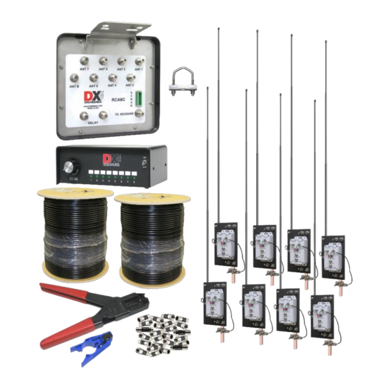
- Page 1 Receive Eight Circle Array Complete System Package DXE-R8C-SYS-V3 U.S. Patent No. 7,423,588 DXE-R8C-SV3-INS Revision 0 © DX Engineering 2022 1200 Southeast Ave. - Tallmadge, OH 44278 USA Phone: (800) 777-0703 ∙ Tech Support and International: (330) 572-3200 E-mail: DXEngineering@DXEngineering.com...
-
Page 2: Table Of Contents
Table of Contents Introduction Are you ready to build your Receive Eight Circle Array? DXE-R8C-SYS-V3 Complete System Package Additional Parts Required, Not Supplied with the DXE-R8C-SYS-V3 Eight Circle Layout System Overview Installation Control and Power Connections Receive Eight Circle Active Vertical Elements... -
Page 3: Introduction
Low current DC powered control console allows system operation without AC power mains The DXE-R8C-SYS-V3 is a complete Receive Eight Circle Antenna Array Package that can be installed as a Mono-Band or Multi-Band system for 160 through 40 meters using a recommended or alternative array radius for the frequency coverage desired. -
Page 4: Dxe-R8C-Sys-V3 Complete System Package
Array Performance, Site Selection and Sizing the Array. 2. Are you ready to build your system? Proceed! The DXE-R8C-SYS-V3 Receive Eight Circle Array Packages includes: DXE-RCA8C-1 Receive Eight Circle Array Controller DXE-CC-8A Special eight position Receive Eight Circle Control Console modified to provide +12 Vdc for powering the active antennas. -
Page 5: System Overview
America, with elements installed as shown. A mirror image of this element positioning would achieve a typical default North-West for European installations. Figure 1 - Typical Diagram of the DXE-R8C-SYS-V3 Receive Eight Circle Array System System Overview The DXE-R8C-SYS-V3 system is comprised of the modified DXE-CC-8A Eight Position Control Console, the DXE-RCA8C-1 Receive Eight Circle Array Controller, eight DXE-RSEAV-1 Receive Short Element Active Vertical Antennas and one Delay Cable with F-Connectors installed. -
Page 6: Installation
Installation The RCA8C-1 Receive Eight Circle Array Controller can be mounted to a customer supplied galvanized steel pipe driven into the ground at the center of the array. A galvanized pipe ranging from 1 to 2 inch OD may be used. The length of the controller unit's mounting pipe is dependent on your location. - Page 7 A 2.1 mm power cord is supplied with unit. The wire with the white stripes is the +12 Vdc. Outer Connection is GROUND Center Pin is +12 VDC. Figure 4 - Connections between the RCA8C-1 and the modified CC-8A The RCA8C-1 uses a removable five terminal plug as shown in Figure 5. The RCA8C-1 connections are labeled “G A B C D”.
- Page 8 Table 1 - Modified CC-8A Output Truth Table (1 = +12VDC) Control lines (usually BCD ) can normally use good quality CAT5e cable (4 twisted pairs of 24 AWG wire) for runs up to 1000 feet. Typical DX Engineering BCD control lines requirements are +12 VDC at 25 milliamps.
-
Page 9: Receive Eight Circle Active Vertical Elements
2,000 feet Receive Eight Circle Active Vertical Elements The DXE-R8C-SYS-V3 Eight Circle Array is supplied with one DX Engineering model DXE- RSEAV-8 which consists of eight identical DXE-RSEAV-1 Receive Short Element Active Vertical antennas. Featuring the updated DXE-AVA-3 Active Matching Units, the RSEAV antenna offer excellent broadband receiving performance from 100 kHz to 30 MHz. -
Page 10: Ground System
Consult lightning protection and station grounding information in the ARRL handbooks, or by referring to the NEC (National Electric Code). The DX Engineering website also has technical and product information “Lightning Protection and Grounding”. Use lightning surge protectors for the coax feedline and control lines such as the DXE-RLP-75FF Lightning Protector, Receive 75Ω, DC... -
Page 11: Array Spacing
Note: The DXE-R8C-SYS-V3 Eight Circle Receiving Array System should be separated from transmitting or other antennas and structures (particularly metal) by at least 1/2 wavelength. -
Page 12: Vertical Element Feedlines
DX Engineering array, and specifically designed for the DXE- RG6UFQ -1000 flooded cable are the DXE-EX6XL-25 F connectors, which contains 25 quad shield connectors; enough for the entire array plus spares. The DXE-EX6XL connectors cannot be installed with normal crimping tools or pliers. -
Page 13: Typical Dxe-R8C-Sys-V3 Receive Eight Circle Configuration
Typical DXE-R8C-SYS-V3 Receive Eight Circle Configuration Figure 7 Coaxial Cables are shown in various colors for clarity. Shown with optional DXE-RPA-2 Receive Pre- Amplifier, DXE-RFCC-1 Receive Feedline Current Choke and optional DXE-CW9S Control Cable. Power connection to the modified DXE-CC-8A Control Console is not shown. -
Page 14: Delay Line
If you intend to size your array for frequency coverage other than 80 and 160 meter operation, see the section on “Delay Line”. The DX Engineering DXE-RCA8C-1 uses a time delay system, not a traditional phasing system. The delay line length is dictated by array dimensions rather than operating frequency, which allows for the use of a single delay line for optimum directivity over a very wide frequency range. -
Page 15: Theory Of Operation Of The Receive Eight Circle Array
System Design Features and Benefits The DX Engineering Receive Eight Circle Array System designed by W8JI offers the best directional receiving performance in proportion to the space required. Advanced design makes the DX Engineering’s Eight Circle Array, with stable, clean, narrow and low-angle pattern in eight selectable directions, the ultimate receiving antenna. -
Page 16: Frequency Coverage -Vs.- Element Type
However, this Active Element end-fire/broadside array alternative to building a phased Beverage array requires a lot less space and a lot less maintenance! Contact DX Engineering for more details on the use of the DXE-RCA8C-1 for a four element system. -
Page 17: Receive Antennas - Gain And Efficiency
Receive Antennas – Gain and Efficiency One popular misconception is that antenna gain pays equal dividends in receiving and transmitting. While transmit to receive antenna gain reciprocity applies to changes in absolute signal levels, it does not apply to signal-to-noise. Once external noise levels are slightly above receiver noise floor, signal-to-noise ratio is almost entirely a function of antenna pattern. -
Page 18: Effects On Patterns
There is no detrimental effect when a higher frequency array of small receiving elements is placed inside the circle of a lower frequency array of short elements. Note: The DXE-R8C-SYS-V3 Eight Circle Receiving Array System should be separated from transmitting or other antennas and structures (particularly metal) by at least 1/2-wavelength. -
Page 19: Proximity To Transmitting Antennas
Noise that limits the ability to hear a weak signal on the lower bands is generally a mixture of local ground wave and ionosphere propagated noise sources. Some installations suffer from a dominant noise source located close to the antennas. Noise level differences between urban and rural locations can be more than 30 dB during the daytime on 160 meters. -
Page 20: Examples Of Array Performance
DXE-TVSU-1B to ensure the correct transmit to receive switching. Examples of Array Performance The DXE-R8C-SYS-V3 Eight Circle Array System occupies less space than phased Beverage arrays and is much easier to install, is less conspicuous and operates over a wider frequency range with similar or better performance. -
Page 21: Multi-Band Arrays With Active Elements
Multi-Band Arrays with Active Elements Only the DX Engineering Active Receive Verticals or vertical elements with Active Matching Units, with constant 75Ω impedance and unsurpassed dynamic range across the frequency range, will allow a user to properly cover more than one band with the Eight Circle Array. - Page 22 The azimuth patterns in Figure 10 were generated using EZNEC+ and show the effects on the patterns when varying the radius of the array. These patterns are not to be viewed as pointing in a default or particular direction. Figure 10 - 22 -...
-
Page 23: Delay Line
(VF) is very important. We strongly recommended the use of DX Engineering DXE-RG6UFQ- 1000 High Quality, Low Loss, Quad Shield, 75Ω RG6 type Direct Bury Coax "Flooded" Coax. The DX Engineering DXE-RG6UFQ-1000 75Ω quad shield coaxial cable has a nominal VF of ®... -
Page 24: Topographical Considerations
Table 4 – Example delay line length calculation results for a 3:1 or greater frequency coverage The DX Engineering DXE-RCA8C-1 uses a time delay system, not a traditional phasing system. The delay line length is dictated by array dimensions rather than operating frequency, which allows for the use of a single delay line for optimum directivity over a very wide frequency range. -
Page 25: Sizing The Array
Sizing the Array If there are no space constraints, follow the dimensional recommendations in Table 5 for excellent performance. Only a monoband array may be installed with passive verticals or Active Vertical elements, but a multi-band Eight Circle Array must be installed with Active Vertical elements. As demonstrated in the previous sections, an Eight Circle Array that is optimized for a certain band will not yield useful results on the next higher frequency band. - Page 26 Endfire Broadside Radius of Circle Spacing Spacing Diameter, Radius of Distance One Half Endfire Circle[feet] = 1/2 Between Distance Diameters Spacing & Broadside Freq distance between Antennas Between of Circles Broadside Spacing as antennas divided by = 246/F Antennas [feet] Spacing a % of WL sin 22.5 degrees...
-
Page 27: Receive Eight Circle Troubleshooting
Receive Eight Circle Troubleshooting There are several possible causes for a malfunction of a DX Engineering Receive Eight Circle System. Testing the system is not difficult and can be completed in an hour or so. Separate circuits for directional switching, Active Vertical Antenna power, and antenna phasing can each be affected by a variety of cabling, connection and or component problems. - Page 28 installed F connector should have the center conductor protruding 1/4 inch beyond the shell when viewed from the side. Check all F connectors! C) Shorted or opened conductors caused by water migration into a control line or a feedline. Over 80% of all Receive Eight Circle malfunctions have been caused by the above system problems. A thorough inspection and subsequent testing of each control cable, RF cable, and their respective connections, will uncover the cause of most Receive Eight Circle troubles.
- Page 29 If the modified DXE-CC-8A has only a couple LEDs lit with the control cable disconnected, then it may have sustained lightning pulse damage and will need to be repaired or replaced. A new modified DXE-CC-8A is available from DX Engineering. Continue troubleshooting the array control with a good modified DXE-CC-8A or by using a 1A fused power source.
- Page 30 At this point, the problem in your system should have been identified. If you need additional assistance from DX Engineering, feel free to call or write. Detailed discussions of system function, connections, and troubleshooting is best handled by telephone, Monday through Friday, 8:30 am to 4:30 pm Eastern Time, at 330-572-3200.
- Page 31 NOTES: - 31 -...
-
Page 32: Technical Support And Warranty
All products manufactured by DX Engineering are warranted to be free from defects in material and workmanship for a period of one (1) year from date of shipment. DX Engineering’s sole obligation under these warranties shall be to issue credit, repair or replace any item or part thereof which is proved to be other than as warranted;...
Need help?
Do you have a question about the DXE-R8C-SYS-V3 and is the answer not in the manual?
Questions and answers