Table of Contents
Advertisement
Quick Links
Advertisement
Table of Contents
Troubleshooting

Summary of Contents for Asterion HYBRID 30K
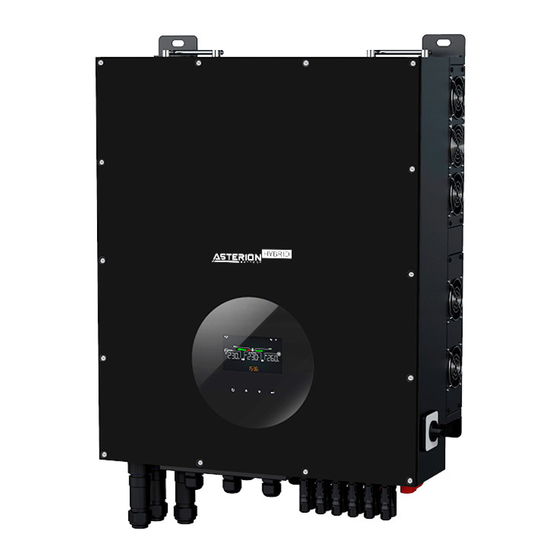
- Page 1 USER MANUAL Inverter/charger ASTERION HYBRID 30K Version: 1.0...
-
Page 2: Table Of Contents
Table Of Contents Introduction ....................4 Important Safety Warning ................5 Unpacking & Overview ................. 7 3-1. Packing List .................... 7 3-2. Product Overview ................... 7 Installation ..................... 7 4-1. Precaution ....................8 4-2. Selecting Mounting Location ..............8 4-3. Mounting Unit ..................8 Grid (Utility) Connection ................10 5-1. - Page 3 19. Specifications ....................71 Appendix I: Parallel Installation Guide ...............73 Introduction....................73 Parallel cable ....................73 Overview .....................73 Mounting the Unit ..................74 Wiring Connection ..................74 Inverters Configuration ................76 Setting and LCD Display ................78 Commissioning ....................81 Trouble shooting ..................82 Appendix II: BMS ....................83...
-
Page 4: Introduction
1. Introduction This hybrid PV inverter can provide power to connected loads by utilizing PV power, utility power and battery power. Electric grids Hybrid inverter Distribution Box PV modules Load Battery Figure 1 Basic hybrid PV System Overview Depending on different power situations, this hybrid inverter is designed to generate continuous power from PV solar modules (solar panels), battery, and the utility. -
Page 5: Important Safety Warning
2. Important Safety Warning Before using the inverter, please read all instructions and cautionary markings on the unit and this manual. Store the manual where it can be accessed easily. This manual is for qualified personnel. The tasks described in this manual may be performed by qualified personnel only. - Page 6 CAUTION! Under high temperature environment, the cover of this inverter could be hot enough to cause skin burns if accidentally touched. Ensure that this inverter is away from normal traffic areas. CAUTION! Use only recommended accessories from installer. Otherwise, not- qualified tools may cause a risk of fire, electric shock, or injury to persons.
-
Page 7: Unpacking & Overview
3. Unpacking & Overview 3-1. Packing List Before installation, please inspect the unit. Be sure that nothing inside the package is damaged. You should have received the following items inside of package: Inverter unit PV connectors AC connectors Fixing screws Parallel cable Software CD Manual... -
Page 8: Precaution
4-1. Precaution This Hybrid inverter is designed for indoor or outdoor use (IP65), please make sure the installation site meets below conditions: ⚫ Not in direct sunlight ⚫ Not in areas where highly flammable materials are stored. ⚫ Not in potential explosive areas. ⚫... - Page 9 1. Drill four holes in the marked 2. Fix the inverter on the wall. locations with supplied four screws. reference tightening torque is 35 N.m. 3. Check if the inverter is firmly secured.
-
Page 10: Grid (Utility) Connection
4. Grid (Utility) Connection 5-1. Preparation NOTE: The overvoltage category of the AC input is III. It should be connected to the power distribution. NOTE2: The inverter is built in a 63A/400V breaker to protect the inverter from AC power damage. WARNING! It's very important for system safety and efficient operation to use appropriate cable for grid (utility) connection. - Page 11 (E) according to polarities indicated on it and tighten the screws to fix wires after connection. L1→ LINE 1 (Black) L2→ LINE 2 (Grey) L→ LINE 3 (Brown) → Ground (Yellow-Green) N→ Neutral (Blue) The reference tightening torque is 4-5 N.m. Step 6: Push protective dome (D) on to socket element (E) until both are locked tightly.
-
Page 12: Generator Connection
6. Generator Connection 6-1. Preparation NOTE: An additional disconnection device should be placed on in the building wiring installation. WARNING! It's very important for system safety and efficient operation to use appropriate cable for AC connection. To reduce risk of injury, please use the proper recommended cable size as below. - Page 13 L1→ LINE 1 (Black) L2→ LINE 2 (Grey) L→ LINE 3 (Brown) → Ground (Yellow-Green) N→ Neutral (Blue) The reference tightening torque is 4-5 N.m. Step 6: Push protective dome (D) on to socket element (E) until both are locked tightly.
-
Page 14: Pv Module (Dc) Connection
7. PV Module (DC) Connection NOTE1: The overvoltage category of the PV input is Ⅱ. NOTE2: Please use 1000VDC/35A circuit breaker. Please follow below steps to implement PV module connection: WARNING: Because this inverter is non-isolated, only two types of PV modules are acceptable: single crystalline and poly crystalline with class A-rated. - Page 15 Male terminal Crimping tool and spanner Cable preparation and connector assembly process: Strip two cables 8 mm on one side and be careful NOT to nick conductors. Insert striped cable into female terminal and crimp female terminal as shown below charts. Insert assembled cable into female connector housing as shown below charts.
- Page 16 The reference Nut cap locking force is 2.0~2.5Nm. Step 4: Check correct polarity of connection cable from PV modules and PV input connectors. Then, connect positive pole (+) of connection cable to positive pole (+) of PV input connector. Connect negative pole (-) of connection cable to negative pole (-) of PV input connector.
- Page 17 Recommended PV module Configuration Module Total Solar input Solar input Q'ty Spec. input Solar input 2 modules (reference) power 250Wp 12pieces in Χ Χ 3000W 12pcs Vmp: series 36.7Vdc 12pieces in - Imp: 6.818A series Χ Χ 6000W 24pcs - Voc: 44Vdc 2 strings in - Isc: 7.636A parallel...
-
Page 18: Battery Connection
20pieces in 20pieces 20pieces in series series series 30000W 120 pcs 2 strings in strings 2 strings in parallel parallel parallel 8. Battery Connection CAUTION: Before connecting to batteries, please install separately a DC circuit breaker between inverter and batteries. NOTE1: Please only use sealed lead acid battery, vented and Gel battery, lithium battery. -
Page 19: Load (Ac Output) Connection
9. Load (AC Output) Connection 9-1. Preparation CAUTION: To prevent further supply to the load via the inverter during any mode of operation, an additional disconnection device should be placed on in the building wiring installation. WARNING! It's very important for system safety and efficient operation to use appropriate cable for AC connection. - Page 20 L1→ LINE 1 (Black) L2→ LINE 2 (Grey) L3→ LINE 3 (Brown) → Ground (Yellow-Green) N→ Neutral (Blue) The reference tightening torque is 1.0-1.5 N.m. Step 4: Push protective dome (D) on to socket element (E) until both are locked tightly.
-
Page 21: Communication Connection
10. Communication Connection Serial Connection The inverter is equipped with several communication ports and it is also equipped with a slot for alternative communication interfaces in order to communicate with a PC with corresponding software. This intelligent slot is suitable to install with SNMP card and Modbus card. -
Page 22: Electric Parameter
11-1. Electric Parameter Parameter Symbol Max. Unit Relay DC voltage Relay DC current Note: The application of the dry contact should not exceed the electric parameter shown as above. Otherwise, the internal relay will be damaged. 11-2. Function Description Unit Condition Dry contact port: Status... -
Page 23: Application With Energy Meter
12. Application with Energy Meter With Modbus card II and energy meter, hybrid inverter can be easily integrated into the existing household system. For details please refer to Modbus card II manual. Note: this application is only valid for Grid-Tie with Backup II mode. Equipped with Modbus card II, hybrid inverter is connected to energy meter with RS485 communication port. -
Page 25: Commissioning
13. Commissioning Step 1: Check the following requirements before commissioning: ⚫ Ensure the inverter is firmly secured ⚫ Check if the open circuit DC voltage of PV module meets requirement (Refer to Section 6) Check if the open circuit utility voltage of the utility is at approximately same ⚫... -
Page 26: Initial Setup
14. Initial Setup Before inverter operation, it’s required to set up “Operation Mode” via software. Please strictly follow below steps to set up. For more details, please check software manual. Step 1: After turning on the inverter and installing the software, please click “Open Monitor”... - Page 27 Off-Grid: PV power only provides power to the load and charge battery. No feed- in back to grid is allowed. SECTION A: Standard: It will list local grid standard. It’s requested to have factory password to make any modifications. Please check local dealer only when this standard change is requested.
- Page 28 in ”Charging source”. It’s not allowed to modify here. When “Grid and PV” or “Grid or PV” is selected in charging source section, this option is default selected. Under Grid-tie mode, this option is invalid. Allow to feed-in to the Grid: This option is only valid under Grid-tie and Grid-tie with backup modes.
- Page 29 Battery charging source: 1. PV and Grid (Default) It’s allowed to charge battery from PV power first. If it’s not sufficient, grid will charge battery. 2. PV only It is only allow PV power to charge battery. 3. None It is not allowed to charge battery no matter it’s from PV power or grid. Load supply source: When PV power is available: 1 PV, 2...
- Page 30 PV energy supply priority setting: 1 Load, 2 Battery and 3 Grid. PV power will provide power to the load first. Then, it will charge battery. If there is any remaining power left, it will feed-in to the grid. Battery charging source: 1.
- Page 31 • Grid-tie with backup (III): PV energy supply priority setting: 1 Load, 2 Grid and 3 Battery PV power will provide power to the load first. If there is more PV power available, it will feed-in to the grid. If feed-in power reaches max. feed-in power setting, the remaining power will charge battery.
- Page 32 not available, battery power will provide power backup. 2. 1 Battery, 2 Grid: Battery power will provide power to the load at first. If battery power is running out, grid will back up the load. NOTE: This option will become ineffective during AC charging time and the priority will automatically become 1 Grid and 2 Battery order.
- Page 33 to the loads. The remaining PV power will feed to the grid. NOTE: The max. feed-in grid power setting is available in parameter setting. Please refer to software manual. Battery charging source: PV and grid charge battery PV power will charge battery first during off-peak time. If it’s not sufficient, grid will charge battery.
- Page 34 Off-Grid Off-Grid (I): Default setting for off-grid mode. PV energy supply priority setting: 1 Load, 2 Battery PV power will provide power to the load first and then charge battery. Feed-in to the grid is not allowed under this mode. At the same time, the grid relay is connected in Inverter mode.
- Page 35 When PV power is not available: 1. 1 Grid, 2 Battery Grid will provide power to the load at first. If grid is not available, battery power will provide power backup. 2. 1 Battery, 2 Grid (Default) Battery power will provide power to the load at first. If battery power is running out, grid will back up the load.
- Page 36 NOTE: It’s allowed to set up AC charging duration. Load supply source: When PV power is available: 1 PV, 2 Grid, 3 Battery PV power will provide power to the load first. If it’s not sufficient, grid will provide power to the load. If grid is not available at the same time, battery power will back When PV power is not available: 1.
- Page 37 Battery charging source: 1. PV or Grid: If there is remaining PV power after supporting the loads, it will charge battery first. Only until PV power is not available, grid will charge battery. 2. PV only: It is only allow PV power to charge battery. 3.
-
Page 38: Operation
15. Operation 15-1. Interface The operation LCD panel, shown in the chart below, includes four touchable function keys and a LCD display to indicate the operating status and input/output power information. LCD display Touchable function keys NOTICE: To accurately monitor and calculate the energy generation, please calibrate the timer of this unit via software every one month. - Page 39 Display Function Indicates input voltage frequency. V: voltage, Hz: frequency, L1/L2/L3: Line phase Indicates AC output power, voltage, and frequency. KW: active power, V: Voltage, Hz: frequency, L1/L2/L3: AC output phase Indicates PV input voltage or power. KV/V: voltage, KW: power, P1: PV input 1, P2: PV input 2, P3: PV input 3...
-
Page 40: Button Definition
Indicates overload. Indicates parallel operation is working. M: Master, S: Slave Allow AC and PV power to charge. Only PV energy is allowed to charge. 15-3. Button Definition Button Operation Function Enter query menu. If it’s in query menu, press this Short press. -
Page 41: Lcd Setting
15-4. LCD Setting After touching and holding “UP” and “DOWN” buttons for 2 seconds, the unit will enter setting mode. Press “UP” or “DOWN” button to select setting programs. And then, press “ENTER” button to confirm the selection or “ESC” button to exit. Program Description Selectable option... - Page 42 Select “LIb” using LIb-protocol compatible battery Lithium battery compatible protocol. selected, programs of 4, 7, 8 and 9 will be automatically set up. No need for further setting. party Lithium battery If selected, programs of 4, 7, 8 and 9 will be automatically set up.
- Page 43 Default setting: 788V Setting range is from Floating 760V to 900V. Increment charging voltage of each click is 1V. Default setting: 568V Setting range is from 300V to 800V. Increment of each click is 1V. Low DC cut off battery voltage SOC 10% (default) If any lithium battery is...
- Page 44 voltage or SOC Increment of each click is percentage when grid available SOC 80%(default) If any lithium battery is selected in program 03, setting value will change automatically. Setting range is from 10% to 100%. Increment of each click is 5%. Grid-tie with backup...
- Page 45 Grid-tie with backup Mode Grid-tie with backup I Battery-Load-Grid: PV power will charge battery first, then provide power to the load. If there is any remaining power left, it will feed-in to the grid. Grid-tie with backup II Load-Battery-Grid: PV power will provide power to the load first.
- Page 46 Feed-in to the grid is not allowed under this mode. The grid relay is NOT connected in Inverter mode. Grid-Tie Mode PV power only feeds-in to the grid. No priority setting is available. Solar If there is remaining PV power Utility(default) after supporting the loads, it will Charger...
- Page 47 available at the same time, battery power will back up. Solar-Battery-Grid: PV power will provide power to the load first. If it’s not sufficient, battery power will provide power to the load. When battery power running out or not available, grid will back up the load.
- Page 48 output on on is from 00:00 to 23:00. Increment of each click is 1 hour. 00:00 (Default) setting range Scheduled scheduled time for AC output time for AC off is from 00:00 to 23:00. output off Increment of each click is 1 hour.
- Page 49 Single: This inverter is Parallel: This inverter is used single phase operated in parallel system. application(default) output mode Disable (default) Enable Generator as AC source Disable (default) Enable Wide input range Disable (default) Enable relay close battery mode For minute setting, the range Time setting is from 00 to 59.
- Page 50 second SOC 10%(default) If any lithium battery is (L2) selected in program 03, output. setting value will change to SOC automatically. Setting range is from 5% to 100%. Increment of each click is Setting Disable(default) Setting range is disable and discharge then from 5 min to 990 min.
-
Page 51: Query Menu Operation
15-5. Query Menu Operation The display shows current contents that have been set. The displayed contents can be changed in query menu via button operation. Press ‘Enter’ button to enter query menu. There are three query selections: ⚫ Input voltage and frequency of AC input. ⚫... - Page 52 ⚫ Input voltage and power of PV input. Procedure Switch LCD Displayed Information The LCD display information will be switched in turns by pressing “Up” or “Down” key. The selectable information is switched as the following table in order. Selectable LCD display information Battery voltage=820V, Battery percentage=90%...
- Page 53 R-phase input voltage=230V, Frequency=50.0HZ Input information (R-voltage, S-voltage, T-voltage, switch every 5 second ) Main R-phase output voltage=230V, Frequency=50.0HZ Defaul Displa Output Scree information (R-voltage, S-voltage, T-voltage, total power, Second output (L2) R-power, R-phase output voltage=230V, Frequency=50.0HZ S-power, T-power switch every 5 second )
- Page 54 R-phase output total power=800w Output information (R-voltage, S-voltage, T-voltage, total power, R-power, S-power, T-power switch every 5 second ) Output Total power=3kw information Output information (R-voltage, S-voltage, Defaul T-voltage, total power, Displa R-power, S-power, Scree T-power switch every 5 second ) PV1 input voltage=900V, PV1 input current=7A PV1 input power=6300W input...
- Page 55 Real date: 2021-11-10 Defaul Displa Real Date Scree Real time: 11:10 Real time PV energy generated today =8Wh. PV energy generated today...
- Page 56 PV energy generated this month = 8kWh. PV energy generated this month PV energy generated this year = 108kWh PV energy generated this year Total PV energy generated = 108kWh. Total energy generated...
- Page 57 Main CPU version 01.01. Main version checking Secondary CPU version 01.01. Secondary version checking Firmware version 16.00 Firmware version checking...
-
Page 58: Operation Mode & Display
Warning code: 06 Warning code 15-6. Operation Mode & Display Inverter mode with grid connected This inverter is connected to grid and working with DC/INV operation. LCD Display Description PV power is sufficient to charge battery, provide power to loads, and then feed in to the grid. - Page 59 LCD Display Description This inverter disabled generate power to the loads via AC output. PV power is sufficient to charge battery first. Remaining PV power will feed in back to grid. This inverter disabled generate power to the loads via AC output.
- Page 60 LCD Display Description PV power and utility are providing power to the connected loads because of insufficient PV power. battery icon flashes indicated that battery connected. Inverter mode without grid connected This inverter is working with DC/INV operation and not connecting to the grid. LCD Display Description PV power is sufficient to charge...
- Page 61 Bypass mode The inverter is working without DC/INV operation and connecting to the loads. LCD Display Description Only utility is charging battery and providing power to connected loads. Only utility is available to provide power to connected loads. The battery icon flashes to indicated that battery is not connected.
- Page 62 LCD Display Description If PV, battery or utility icons are flashing, it means they are not within acceptable working range. If they are not displayed, it means they are not detected.
-
Page 63: Charging Management
16 Charging Management Charging Parameter Default Value Note It can be adjusted via Charging current software from 10Amp to 50Amp. It can be adjusted via Floating charging voltage software from 400Vac to 828.0 Vdc (default) 950Vdc. It can be adjusted via Max. - Page 64 If using sealed lead acid battery, please set up the max. charging current according to below formula: The maximum charging current = Battery capacity (Ah) x 0.2 For example, if you are using 250 Ah battery, then, maximum charging current is 250 x 0.2=50 (A).
-
Page 65: Maintenance & Cleaning
17. Maintenance & Cleaning Check the following points to ensure proper operation of whole solar system at regular intervals. ⚫ Ensure all connectors of this inverter are cleaned all the time. Before cleaning the solar panels, be sure to turn off PV DC breakers. ⚫... -
Page 66: Trouble Shooting
18. Trouble Shooting When there is no information displayed in the LCD, please check if PV module/battery/grid connection is correctly connected. NOTE: The warning and fault information can be recorded by remote monitoring software. 18-1. Warning List There are 20 situations defined as warnings. When a warning situation occurs, icon will flash and will display warning code. -
Page 67: Fault Reference Codes
Stop discharging Informs inverter stop battery discharging battery. Stop charging battery Informs inverter to stop charging battery Charge battery Informs inverter charge battery. 18-2. Fault Reference Codes When a fault occurs, refer to below table to solve problem. Situation Fault Solution Fault Event Possible cause... - Page 68 Solar input power Solar input 1. Please check if solar abnormal driver damaged. input voltage is higher than Solar input 850V. power is too much Please contact your when voltage is installer. more than 850V. Solar over current Surge 1. Restart the inverter. 2.
- Page 69 circuited. well and remove abnormal load. Fan lock Fan failure Please contact your installer. sensor Internal Please contact your fault components installer. failure S phase INV DC Utility fluctuates. 1. Restart the inverter. current over 2. If the error message still remains, please contact...
- Page 70 voltage high components installer. failed. Incompatible Inverter hardware Please contact your inverter firmware does not match installer. firmware. Exit battery over Exit battery Check ambient temperature temperature is too temperature and fans. high. 2. If the error message still remains, please contact your installer.
-
Page 71: Specifications
19. Specifications MODEL ASTERION HYBRID 30K RATED OUPUT POWER 30000W PV INPUT (DC) Max. PV Power 40000W Nominal DC Voltage 720Vdc Max. Array Open 1000 VDC Circuit Voltage Working voltage range 350 ~ 1000 VDC MPPT Range @ Operating 350 VDC~900 VDC... - Page 72 BATTERY MODE OUTPUT (AC) Nominal Output Voltage 220/230/240 VAC Output Waveform Pure Sine Wave Efficiency (DC to AC) Output Power 30000W BATTERY & CHARGER Nominal DC Voltage 736 VDC Maximum Charging Current GENERAL Dimension, D X W X H 255 x 660 x 750 (mm) Net Weight (kgs) INTERFACE...
-
Page 73: Appendix I: Parallel Installation Guide
Appendix I: Parallel Installation Guide Introduction This inverter can be used in parallel with maximum 6 units. Parallel cable You will find the following items in the package: Parallel communication cable Current sharing cable Overview 1. Parallel communication port 2. Current sharing port... -
Page 74: Mounting The Unit
Torque ASTERION 1*4AWG 5.5~7 Nm HYBRID 30K WARNING1: Be sure the length of all battery cables is the same. Otherwise, there will be voltage difference between inverter and battery to cause parallel inverters not working. WARNING2: The battery of each inverter must be independent. - Page 75 200A/230VAC HYBRID 30K Note1: Also, you can use 50A breaker for ASTERION HYBRID 30K for only 1 unit and install one breaker at its AC input in each inverter. Note2: Regarding three-phase system, you can use 4-pole breaker directly and...
-
Page 76: Inverters Configuration
Inverters Configuration Two inverters in parallel: Power Connection Load OUTPUT OUTPUT GRID GRID BAT+ BAT- BAT+ BAT- Communication Connection Three inverters in parallel: Power Connection... - Page 77 Load OUTPUT OUTPUT OUTPUT GRID GRID GRID BAT+ BAT- BAT+ BAT- BAT+ BAT- Communication Connection Four inverters in parallel: Power Connection Load OUTPUT OUTPUT OUTPUT OUTPUT GRID GRID GRID GRID BAT+ BAT- BAT+ BAT- BAT+ BAT- BAT+ BAT- Communication Connection...
-
Page 78: Setting And Lcd Display
Setting and LCD Display Setting Program: The parallel function setting is only available by SolarPower. Please install SolarPower in your PC first. For setting, you can set the inverter one by one through RS232 or USB port. But we suggest to use SNMP or Modbus card to combine the system as a centralized monitoring system. - Page 79 If you want to use parallel function, please choose “Enable” and press “ ” button. Then, “ ” button will be shown is the screen. Please be sure to click “ ” button before clicking “ ” button. There is a “Sync” button in each parameter setting. When “Sync” is clicked and “Apply”...
- Page 80 Parallel for output: Disable Fault code display: Fault Fault Event Icon on Code Power feedback protection Firmware version inconsistent Current sharing fault CAN fault Host loss Synchronization loss...
-
Page 81: Commissioning
Commissioning Step 1: Check the following requirements before commissioning: ⚫ Correct wire connection. ⚫ Ensure all breakers in Line wires of load side are open and each Neutral wire of each unit is connected together. Step 2: Turn on each unit and set “enable parallel for output” on SolarPower or SolarPower Pro. -
Page 82: Trouble Shooting
Trouble shooting Situation Solution Fault Fault Event Description Code Remove excessive loads. Restart the inverter. Over current on Neutral wire If the problem remains, please contact your installer. Restart the inverter. Check if L1/L2/L3/N cables are not connected with wrong sequence in Current feedback into the all inverters. -
Page 83: Appendix Ii: Bms
Appendix II: BMS 1. BMS port pin define: Definition PIN 3 RS485B PIN 5 RS485A PIN 8 2. After all wires are connected well and the communication between the inverter and battery is successful, it will show successful icon on the LCD screen. - Page 84 Developer and supplier of https://energon-group.com/ MAN-ASTERION-SOL- energy storage and power ASTERION-HYBRID-30K-221114-EN generation solutions...
Need help?
Do you have a question about the HYBRID 30K and is the answer not in the manual?
Questions and answers