
Related Manuals for Caen ELS WPOLINV200XA

Summary of Contents for Caen ELS WPOLINV200XA
- Page 1 Polarity Inverters 200 A, 400 A, 600 A Polarity Inverters User’s Manual All Rights Reserved © CAEN ELS s.r.l. Rev. 1.2 – November 2022...
- Page 2 This product is & compliant. CAEN ELS s.r.l. c/o AREA Science Park S.S. 14 km 163,5 - 34149 Basovizza (TS) Italy Mail: info@caenels.com Web: www.caenels.com...
- Page 3 This manual covers the following standard models: WPOLINV200XA WPOLINV400XA WPOLINV600XA For technical assistance please refer to the following contact: CAEN ELS S.R.L. SS14 km 163,5 34149 Basovizza (TS) – Italy (c/o Area Science Park – Building Q1) Phone: +39 040 375 6610...
-
Page 4: Table Of Contents
Polarity Inverters – User’s Manual Table of contents INTRODUCTION ....................9 ..............9 OLARITY NVERTER VERVIEW ..................... 11 YSTEM ARTS WPOLINV200XA ..................11 WPOLINV400XA / WPOLINV600XA ............13 INSTALLATION ....................16 ................. 16 REPARATION FOR ..................16 NITIAL NSPECTION ....................17 OUNTING AC I .............. - Page 5 Polarity Inverters – User’s Manual Document Date Comment Revision December 11 , 2017 First Release June 26 , 2022 Added 400/600 A models November 22 , 2022 Added UKCA compliance logo...
- Page 6 Polarity Inverters – User’s Manual Safety information The following table shows the general environmental requirements for a correct operation of referred instruments in this User’s Manual: Environmental Conditions Requirements Environment Indoor Use Operating Temperature 0°C to 45°C Operating Humidity 20% to 80% RH (non-condensing) Altitude Up to 2000 m Pollution degree...
- Page 7 Modules due to negligence on behalf of the User. It is strongly recommended to read thoroughly this User's Manual before any kind of operation. CAEN ELS s.r.l. reserves the right to change partially or entirely the contents of this Manual at any time and without giving any notice.
- Page 8 Polarity Inverters – User’s Manual WARNING • Do not use this product in any manner not specified by the manufacturer. The protective features of this product may be impaired if it is used in a manner not specified in this manual. •...
-
Page 9: Introduction
These polarity inverters are able to reverse currents up to 630 A and so they represent the perfect fit for the CAEN ELS NGPS unipolar power supplies, both in single or paralleled configurations. Each polarity inverter fits in a single 19” 6U crate and it can be controlled via dry contacts while providing to the user information about the correct working of the system and the selected polarity. - Page 10 Polarity Inverters – User’s Manual These polarity inverters have the following ratings listed in Table 1: Model Description Maximum Voltage Maximum Current WPOLINV200XA 200 A Polarity Inverter 250 V 200 A WPOLINV400XA 420 A Polarity Inverter 250 V 420 A...
-
Page 11: System Parts
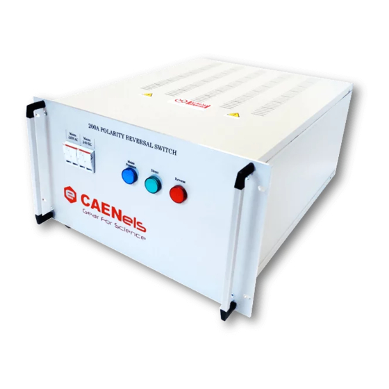
Polarity Inverters – User’s Manual 1.2 System Parts WPOLINV200XA The WPOLINV200XA is housed in a 6U – 19” crate (Figure 2). Figure 2: Front WPOLINV200XA panel. The main parts on the front panel of the polarity inverter are WPOLINV200XA listed below: - Four fuses are installed, two of them connected to the AC mains and the other ones to the rectified 24V mains. - Page 12 The rear panel of the polarity inverter contains the parts related to the control and monitoring of the unit, see Figure 3: Rear WPOLINV200XA panel. Figure 3: Rear WPOLINV200XA panel. The main parts on the rear panel of the polarity inverter are...
-
Page 13: Wpolinv400Xa / Wpolinv600Xa
Polarity Inverters – User’s Manual WPOLINV400XA / WPOLINV600XA The WPOLINV400XA/600XA is housed in a 6U – 19” (Figure 4: Front WPOLINV400XA/600XA panel. Figure 4: Front panel. WPOLINV400XA/600XA The main parts on the front panel of the WPOLINV400XA/600XA polarity inverter models are listed below: - Four fuses are installed, two of them connected to the AC mains and the other ones to the rectified 24V mains. - Page 14 Polarity Inverters – User’s Manual The WPOLINV400XA/600XA polarity inverter models are delivered with a cover, shown in Error! Not a valid bookmark self-reference., to protect the user from accidental contacts on the DC busbars (see Figure 6 WPOLINV400XA/600XA : Rear panel ) during the normal operation.
- Page 15 Polarity Inverters – User’s Manual The rear panel without the cover is shown in Figure 6 WPOLINV400XA/600XA : Rear panel without cover on the DC busbars. Figure 6: Rear panel without cover on the DC busbars. WPOLINV400XA/600XA The main parts on the rear panel of the WPOLINV400XA/600XA polarity inverter models are listed below: - POWER CABLES from the power unit have to be connected to the DC-IN and the load to DC-OUT.
-
Page 16: Installation
Keep all packing material until the inspection has been completed. If damage is detected, compile the RMA form available to the CAEN ELS web site. -
Page 17: Mounting
Polarity Inverters – User’s Manual 2.3 Mounting The polarity inverter is designed to fit in a standard 19” equipment rack. CAUTION Always use L-shelves to correctly sustain the polarity inverter. 2.4 AC Input Power Connections The AC line input connector on the rear panel is the same for all the polarity inverter models, namely an IEC C14 socket [shown in Figure 7(a)]. -
Page 18: Ac Input Cord
Polarity Inverters – User’s Manual AC Input Cord The polarity inverters are directly shipped with the corresponding power cord (suitable for the destination country of the purchase). Polarity Inverter side connector is a standard IEC C14 plug for all the models. Wire size for detachable power supply cord, shall be at least 0.75 mm . -
Page 19: Connections
Ensure that all connections are securely tightened before applying power. The connections mentioned in Section 1.2 are hereafter shown again. WPOLINV200XA Figure 8: Rear panel of the WPOLINV200XA model. The main parts on the rear panel of the polarity inverter are listed WPOLINV200XA below (see Figure 8 : Rear panel of the WPOLINV200XA model.) - Page 20 Polarity Inverters – User’s Manual WPOLINV400XA/600XA Figure 9: Rear panel of WPOLINV400XA/600XA models. The main parts on the rear panel of the polarity inverter WPOLINV400XA/600XA models are listed below (see Figure 9 : Rear panel of WPOLINV400XA/600XA models. - POWER CABLES from the power unit have to be connected to the DC-IN and the load to DC-OUT.
-
Page 21: Power Connectors
Figure 10: blue DC-IN corresponds to blue DC-OUT if the polarity is direct; with respect to the power supply polarity, the blue connection can be either positive or negative. Figure 10: Phoenix Contact HDFKW-95-F/7 (WPOLINV200XA). Figure 11: Phoenix Contact HDFKW-95-F/7 mechanics. -
Page 22: Wpolinv400Xa / Wpolinv600Xa
Polarity Inverters – User’s Manual Hereafter the parameters to be used on such connector are listed: • the acceptable wire section is from 25 to 95 mm • peeling length is 27 mm; • tight force is 20 Nm; • Hex Key is 6 mm; 2.5.1.2 WPOLINV400XA / WPOLINV600XA The 420 A (WPOLINV400XA) and 630 A (WPOLINV600XA) Polarity Inverter... -
Page 23: Control And Monitoring Connector
Polarity Inverters – User’s Manual Control and Monitoring Connector All the polarity inverter models have the same Control and Monitoring connector mounted on the rear panel and labeled as C1 (see Figures Figure 3: Rear WPOLINV200XA and Figure WPOLINV400XA/600XA panel. -
Page 24: Earth Connection
Polarity Inverter. Earth connection With reference to Figure 8 and Figure 9 : Rear panel of the WPOLINV200XA model. for the WPOLINV200XA and Rear panel of WPOLINV400XA/600XA models. WPOLINV400XA/600XA models, respectively, the earth connector (label 8) has to be connected to protective earth as an additional safety procedure. -
Page 25: Technical Specifications
Polarity Inverters – User’s Manual 3. Technical Specifications The main technical Specifications for the available Polarity Inverters are hereafter presented: 200 A 400 A 600 A Rated Current 200 A 420 A 630 A Rated Voltage 250 V 250 V 250 V Auxiliary Input Voltage 100 –... -
Page 26: Mechanical Dimensions
Polarity Inverters – User’s Manual 4. Mechanical Dimensions External mechanical dimensions for the model is shown in WPOLINV200XA echanical dimensions (all dimensions in mm). Figure 14: M echanical dimensions Figure 14: M... - Page 27 Polarity Inverters – User’s Manual External mechanical dimensions for the models is WPOLINV400XA and WPOLINV600XA shown in (all dimensions in mm).
-
Page 28: Control Cable
Polarity Inverters – User’s Manual 5. Control cable With the polarity inverter it is also included the control cable that allow the connection and the control with the NGPS power supply. Hereafter is the cable schematic. See Section 2.5.2 for the pinout of the control and monitoring connector. -
Page 29: Ngps Configuration
Polarity Inverters – User’s Manual 6. NGPS Configuration The polarity inverter can be control with the NGPS power supply if connected with the dedicated cable. The NGPS shall anyhow be configured to control automatically the polarity inverter depending on the current value required: Direct if a positive current set point is required or Revers if a negative current set point is required.
Need help?
Do you have a question about the WPOLINV200XA and is the answer not in the manual?
Questions and answers