
Summary of Contents for Alivida Steam 3
- Page 1 Steam generator for Steam bath/Hammam Installation and User Manual v2.1 1. Warnings General warnings...
-
Page 2: Table Of Contents
Safety Warnings Removal regulations 2. Alivida Steam Kit 3. General description Alivida Steam steam generator Alivida Steam Control Panel 4. System Installation Generator dimensions Installation piping Mechanical installation Steam pipe and steam outlet Water discharge Electrical connections Control panel Temperature sensor... -
Page 3: Safety Warnings
Carefully read all chapters of this manual before installing the steam generator. Keep this manual for the entire life of the product. The Alivida steam generator is designed to humidify steam baths/hammam, by distributing steam. Do not use steamers that are not included in this kit. -
Page 4: Alivida Steam Kit
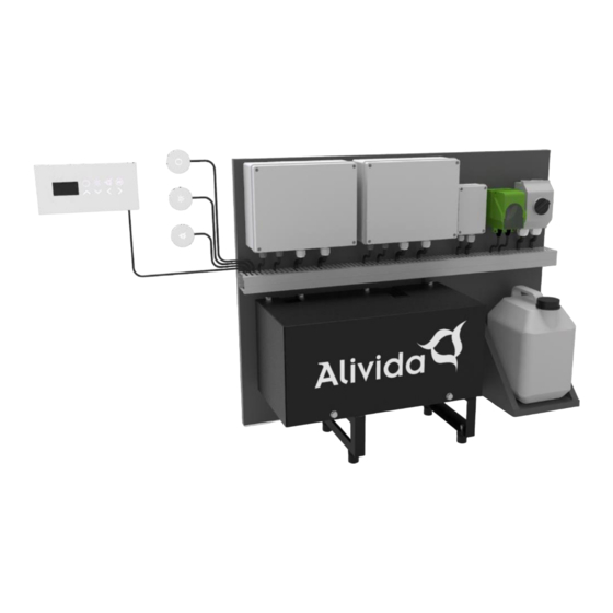
• Alivida Steam kit 3 • Alivida Steam kit 6 • Alivida Steam kit 9 • Alivida Steam kit 12 The Alivida Steam kit consists of the following parts: • Steam generator 2.8 or 5.6 kW • Control panel • Steam outlet •... -
Page 5: General Description
3. General description The Alivida Steam Kit can be used for both home and professional use. The steam generator is operated by means of a touch panel which can be installed both inside and outside the steam cabin. The control system measures the ambient temperature and regulates the production of steam to maintain the user's desired temperature. -
Page 6: System Installation
4. System Installation Important: Before installing the system, it is important to check whether the connections of the piping comply with the regulations. The water inlet, water outlet, and steam outlet must be properly installed. Dimensions... -
Page 7: Installation Piping
The generator must be connected to a drinking water supply. The connections to the water mains must be made in accordance with local laws and regulations. Use pipes with a suitable diameter: Model Water inlet Water outlet Steamoutlet Alivida Steam 3 ½” ½” ½” Alivida steam 6 ½” ½”... -
Page 8: Mechanical Installation
Mechanical installation The steam generator is designed for three types of installations, as shown below: On the wall On a shelf In a niche... - Page 9 Connections Preparation for making the mounting holes. Drill holes in the wall to install the generator mounting bolts Make sure the holes are properly positioned in the wall.
- Page 10 Mounting Mount the generator on the wall. Warning: Use screws each capable of lifting more than 50 kg. Make sure generator is parallel to the wall. Removing the housing Remove the screws as shown in the illustration below. Remove the housing to expose the printed circuit board.
-
Page 11: Steam Pipe And Steam Outlet
Steam pipe and steam outlet The steam line must not have narrowed sections or be fitted with shut-off valves. The pipe must run at a minimum angle of 4° from the generator to the steam outlet. The length of the steam pipe between the generator and the steam outlet must not exceed a total length of 6 meters. -
Page 12: Water Discharge
Water drainage Without narrowed sections, barriers or valves. Minimum slope: 4° Heat resistant material (> 100°C) Siphon... -
Page 13: Electrical Connections
Make sure that the electrical connection corresponds to the specification on the steam generator. Model Power (Watts) Voltage (volts) Alivida Steam 3 2800 1 x 16 Alivida Steam 6 5600 1 x 230 (cooking group) -
Page 14: Control Panel
Control panel Mechanical installation The control panel can be installed on both the inside and outside of the steam bath. A special stainless steel flush-mounted box is used. - Page 15 Display dimensions Electrical installation Plug the male connector of the control panel into the corresponding female connector of the steam generator.
-
Page 16: Temperature Sensor
Temperature sensor Mechanical installation The temperature sensor is held in place by a cylindrical holder, which is installed on the inside of the steam room at a height of +/- 160 cm. Use silicone caulk to mount the holder in place. Stelschroef voor het vastzetten van de temperatuursensor. -
Page 17: Drain Function
Drain option at power up A connection between pin 3 and pin 6 of the M9 connector (AUX IN) ensures that the automatic drain function is switched off when the power is applied to the steam generator. Drain option with steam function DIP Switch 8 ON = No drain cycle is performed at the beginning and end of a steam session. -
Page 18: Remote Start
Remote start The steam generator can be controlled externally by means of a remote contact, for example with a home automation system. A connection between pin 1 and pin 2 of the M9 connector (AUX IN) ensures that the steam generator is switched on in its last setting (for example 30 min.
Need help?
Do you have a question about the Steam 3 and is the answer not in the manual?
Questions and answers