Advertisement
Quick Links
Advertisement

Summary of Contents for I MUST SCREAM 140
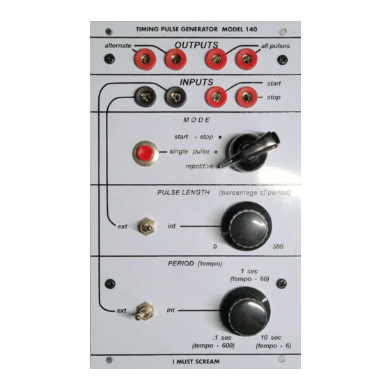
- Page 1 I MUST SCREAM TIMING PULSE GENERATOR MODEL 140 ASSEMBLY GUIDE (SMD VERSION) imustscream.cc...
- Page 2 The kit consists of PCB, Panel, bags of components and knobs.
- Page 3 Step 1 Solder TH polarized capacitors, trimmers and J201 transistor. C4: 4.7uF, C5: 100uF, C1: 1uF. Pay attention to the orientation of the transistor and capacitors.
- Page 4 Step 2 Solder all the pins. This step is (optional). Otherwise, you can solder wires directly. However, I strongly recommend using pins.
- Page 5 Step 3 Remove the anti-rotational tag using wire cutter.
- Page 6 Step 4 Secure banana jacks, push button and switch on the front panel.
- Page 7 Step 5 (identical to through-hole version) Position potentiometers, switches and standoffs. Don’t solder yet. Secure them to the front panel, and tighten. Solder AFTER tightening.
- Page 9 Step 6 (identical to through-hole version) Cut and strip the wires. Pay attention that the colors of wires can be different than you see on photos. First, wire the switch. Connect the pins on the PCB to the pins on switch according to the photo.
- Page 11 Step 7 (identical to through-hole version) Now wire the button. Connect the pins on the PCB to the pins on button according to the letters – A B C.
- Page 13 Step 8 (identical to through-hole version) Wire the banana jacks.
- Page 14 Step 9 It’s a good time to verify all the wiring you have done. If everything is good – move to the last step.
- Page 15 Step 10 Now you can put the knobs on. Congratulations!
Need help?
Do you have a question about the 140 and is the answer not in the manual?
Questions and answers