Advertisement
Quick Links
Advertisement

Summary of Contents for I MUST SCREAM 110
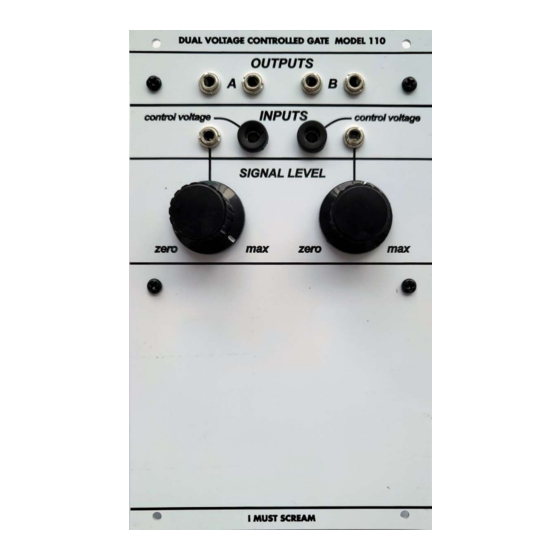
- Page 1 I MUST SCREAM DUAL VOLTAGE CONTROLLED GATE MODEL 110 ASSEMBLY GUIDE imustscream.cc...
- Page 2 The kit consists of PCB, Panel, 3 bags of components (A, B, C) and knobs. Bag (A) contains: resistors, all numbered by their values Bag (B) contains: Capacitors, Trimmers, Transistors. Pay attention to the matched transistors pairs: (T1 T2) and (T8 T9) Bag (C) contains: Jacks, Potentiometers, Banana Jacks, Standoffs, Wire, Pins.
- Page 3 Step 1 Solder all the resistors.
- Page 4 Step 2 Solder all the transistors. Pay attention to the orientation. The flat side has to match with the flat side on the silkscreen. Solder matched pairs in their corresponding places.
- Page 5 Step 3 Solder 2 unpolarized capacitors. Orientation here doesn’t matter.
- Page 6 Step 4 Solder polarized capacitors. Orientation here DOES matter. Refer to silkscreen + sign.
- Page 7 Step 5 Solder trimmers. Pay attention to the orientation. You can refer to the silkscreen or this photo.
- Page 8 Step 6 This step is (optional). Otherwise, you can solder wires directly. However, I strongly recommend using pins.
- Page 9 Step 7 Secure the banana jacks on the front panel.
- Page 10 Step 8 Position jacks, potentiometers and standoffs. Don’t solder yet. Secure them to the front panel, and tighten. Solder AFTER tightening.
- Page 12 Step 9 Cut and strip the wire from the Bag (C). Insert it in the CV pins.
- Page 13 Step 10 Solder wires to the banana jacks.
- Page 14 Step 11 Now you can put knobs on and prepare for simple calibration. Congratulations!