Advertisement
DAE
Installation Manual
Features
DAE sensors have an integral conditioning electronics. Supplied at +24 VDC, they deliver a position-proportional
0...10 VDC output signal. A common return line allows a 3-wire interface.
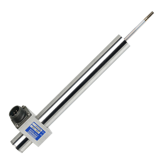
Housing
DAE sensor case is made of stainless steel. The integral electronics is potted for high robustness. The G-
version has ball-eyes on both ends. Non-contact position detection through axial displacement of the linear-
bearing-guided core.
Electrical system
Position sensing is based on the LVDT technique. A moving core rod changes induction in a primary / secondary
configuration, generating a position-proportional signal. The integral electronics converts the signal into a 0 ... 10
VDC output (0 V = core fully inserted, 10 V = core fully retracted). The output requires a load of > 10 kOhm. The
sensor requires a stabilized and filtered +22 ... +26 VDC supply voltage with reverse-polarity protection. Avoid
supply overvoltage and applying a voltage to the output.
The sensor is designed for minimal non-linearity and low temperature coefficient.
Scope of delivery
The sensor is supplied ready-to-use with a mating connector.
Safety
Take all safety measures to avoid damage to personnel or equipment, especially in case of unexpected
functional results.
Installation and operation requires trained personnel.
Check the installed sensor for potential collision with machine parts.
Carefully study this manual carefully.
Installation
Connect the sensor according to the table on the right using
a shielded cable. Connect shielding to control electronics,
not to the sensor.
The sensor is factory-adjusted for optimal linearity over
nominal stroke (at nominal +24 VDC supply voltage and
+20 ... +25°C). Without re-adjustment, install core according
to dimension A given in the sensor test record (if available,
otherwise see DAE data sheet).
Conduct adjustment / measurements with electronics upon
warm-up.
A
B
Connection
C
A
Supply +22...26 VDC
B
Common (0 VDC)
C
Signal output 0...10 VDC
Advertisement
Table of Contents

Summary of Contents for Messotron DAE
- Page 1 0...10 VDC output signal. A common return line allows a 3-wire interface. Housing DAE sensor case is made of stainless steel. The integral electronics is potted for high robustness. The G- version has ball-eyes on both ends. Non-contact position detection through axial displacement of the linear- bearing-guided core.
- Page 2 Installation Manual Adjustment Remove connector for adjustment. Remove core rod (or place core at dimension A) and trim zero-poti “O“ for 5 VDC output. Insert (re- position) core back to obtain the same output signal. Small deviations can be re-adjusted on zero- poti.
Need help?
Do you have a question about the DAE and is the answer not in the manual?
Questions and answers