Table of Contents
Advertisement
Quick Links
Consultation with SebaKMT
User Manual
Correlator
Correlux C-300
Mess- und Ortungstechnik
Measuring and Locating Technologies
Elektrizitätsnetze
Power Networks
Kommunikationsnetze
Communication Networks
Rohrleitungsnetze
Water Networks
Abwassernetze
Sewer Systems
Leitungsortung
Line Locating
1
Issue:
01 (04/2017) - EN
Article number:
85839
Advertisement
Table of Contents

Subscribe to Our Youtube Channel
Summary of Contents for sebaKMT Correlux C-300
- Page 1 Consultation with SebaKMT User Manual Correlator Correlux C-300 Mess- und Ortungstechnik Measuring and Locating Technologies Elektrizitätsnetze Power Networks Kommunikationsnetze Communication Networks Rohrleitungsnetze Water Networks Abwassernetze Sewer Systems Leitungsortung Line Locating Issue: 01 (04/2017) - EN Article number: 85839...
- Page 2 Consultation with SebaKMT...
-
Page 3: Consultation With Sebakmt
SebaKMT All rights reserved. No part of this handbook may be copied by photographic or other means unless SebaKMT have before-hand declared their consent in writing. The content of this handbook is subject to change without notice. SebaKMT cannot be made liable for technical or printing errors or shortcomings of this handbook. -
Page 4: Terms Of Warranty
This warranty does not apply to faults in the software supplied. During the period of warranty, SebaKMT agree to repair faulty parts or replace them with new parts or parts as new (with the same usability and life as new parts) according to their choice. -
Page 5: Table Of Contents
Terms of Warranty Contents Consultation with SebaKMT ................... 3 Terms of Warranty ......................4 Safety Instructions ................... 7 General Safety Instructions and Warnings ............7 General Notes ....................7 Basic principles ....................9 Correlation analysis menu .................. 9 Technical description ..................11 Set components .................... - Page 6 Terms of Warranty 7.3.1 Language ......................26 7.3.2 Green checkmark / red cross ................26 User interface ....................27 Basic settings ....................29 7.5.1 Storage location for software database ............29 7.5.2 GPS receiver port ..................... 29 7.5.3 System of units ....................29 7.5.4 Logarithmic or linear coherence display ............
-
Page 7: Safety Instructions
Safety Instructions Safety Instructions General Safety Instructions and Warnings Do not drop the device / the system’s components or subject it / them to • strong impacts or mechanical shocks. The limits described under Technical Data may not be exceeded. •... - Page 8 Use genuine accessories to ensure system safety and reliable operation. The use of other parts is not permitted and invalidates the warranty. Repair and Repair and maintenance work has to be carried out by SebaKMT or authorised service maintenance partners using original spare parts only. SebaKMT recommends having the system tested and maintained at a SebaKMT service centre once a year.
-
Page 9: Basic Principles
Basic principles Basic principles Correlation analysis menu After the start of a correlation, the result is displayed in the following view: Correlation Coherence Element Description Correlation trace (in the top left in the diagram, the “delay value” is specified. The colours of the numbers indicate the quality of the correlation (green = good, red = poor).) Coherence curve Pipe section between the two sensors... - Page 10 Basic principles Element Description Distance from sensor to leak Comment field for notes on this correlation Side change Side change Click button. The two displayed leak distance specifications switch sides. Enlarge Zoom K to enlarge a section of the correlation trace Click button, then in the diagram highlight the section that needs to be enlarged.
-
Page 11: Technical Description
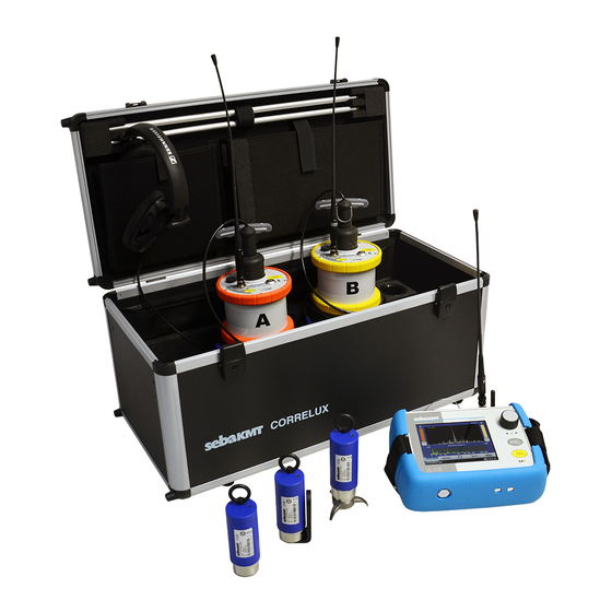
Function Correlux C-300 is a correlator system for the leak localisation in drinking water networks. Pressurised water flowing out at the leak location creates a noise which travels out in all directions of the pipe. -
Page 12: Communication Of The Components
Technical description Offline measurement During an offline measurement, the recording of the measurements and the correlation of the measurement data do not take place at the same time, but instead sequentially: Step Description Programming the Power transmitters and/or Multi sensors Installation of the Power transmitters and/or the Multi sensors at up to 8 measurement points Execution of a noise measurement immediately or at a later time (for example, in... -
Page 13: Technical Data
Technical description Technical data Correlux C-300-RI is specified by the following technical parameters: Interface Parameter Value COR C-300-RI PC-interface Power supply 600 x 110 x 60 mm Dimensions approx. 600 g Weight Power transmitter Parameter Value COR PT-3A/B Sensor Piezo sensor with active amplifier (standard) /... -
Page 14: Included In Delivery
Technical description Parameter Value Ø 45 x 115 mm Dimensions 0.4 kg Weight IP 68 Protection class Included in delivery Standard accessories The scope of delivery of the standard set includes the following devices and accessories: Accessory Description Serial no. COR PT-3A Power transmitter A 1004779... -
Page 15: Cor C-300-Ri Radio Interface
COR C-300-RI radio interface COR C-300-RI radio interface Layout and function The device has the following operating buttons and connection sockets: Element Description Volume buttons For adjusting the headphone volume in 32 levels Left button K Volume down Right button K Volume up Button A/B with indicator lights For selecting which Power transmitter is played back over the connected... -
Page 16: Power Supply
COR C-300-RI radio interface Function The COR C-300-RI device serves as the radio interface between the computer and the Power transmitters or Multi sensors. In addition, the supplied headphones can be connected to the device to listen to the recorded leak noises. Power supply The COR C-300-RI device is supplied with power via the USB connection to the computer. -
Page 17: The Power Transmitters
The Power transmitters The Power transmitters Design and function Each Power transmitter has an active amplifier for the microphone signal, a data memory, a rechargeable Li-Ion battery, a digital radio module and an analogue radio module with antenna inside. The transmitters have the following external characteristics: Element Description Microphone storage place Sensor socket... -
Page 18: Identification Number (Id)
Each Power transmitter has its own six-digit identification number (short: ID). Using this ID the device can be managed and clearly identified in the CorreluxView-3 software and within the SebaKMT-Cloud. The ID is deduced from the last six digits of the device's serial number (short: SN). -
Page 19: Power Supply
Risk of fire! The charging stations are for transport and charging of the devices only. NOTE Any repairs must be carried out by SebaKMT or an authorized service partner. Otherwise, the devices' resistance against water and dirt cannot be guaranteed. -
Page 20: Commissioning
The Power transmitters Commissioning Switching ON/OFF To turn on, briefly press the I/O pushbutton . The I/O LED is lit green when the device is turned on. To turn the device off, press the button until the LED goes out. Stand-by The microphone's storage place is fitted with a magnetic switch. -
Page 21: The Multi Sensors
Each Multi sensor has its own six-digit identification number (short: ID). Using this ID the device can be managed and clearly identified in the CorreluxView-3 software and within the SebaKMT-Cloud. The ID is deduced from the last six digits of the device's serial number (short: SN). -
Page 22: Power Supply
Any repairs must be carried out by an authorized service partner. Otherwise, the devices' resistance against water and dirt cannot be guaranteed. Do not open the devices yourself. If you have problems with the battery, please contact your SebaKMT service partner. -
Page 23: Switching On/Off
The Multi sensors Switching ON/OFF The Multi sensors have an internal magnetic switch. To turn a Multi sensor on, briefly hold a magnet (e.g. the foot of another Multi sensor) in front of the sensor's I/O area . The device turns on. The indicator light flashes 3 times. - Page 24 The Multi sensors Unscrew the magnetic foot from the sensor. Take one of the supplied screws from the Correlux set to screw the angle adapter on the sensor. Make sure that the sensor's type plate does face away from the angle adapter.
-
Page 25: Correluxview-3 Software
Updating the software We recommended that you keep the software current at all times. SebaKMT provides improved versions of the CorreluxView-3 software in the download area of www.sebakmt.com on a regular basis. To perform an update, retrieve the latest software from the download area. After... -
Page 26: Starting The Software
You can also look for and open the software using the Windows start menu: “Start All Programs/All Apps SebaKMT CorreluxView Launch CorreluxView” The start screen After the software is started, a start screen appears for a few seconds. -
Page 27: User Interface
CorreluxView-3 software User interface The CorreluxView screen is divided into three sections - menu bar, directory tree and display area. This screen layout remains unchanged regardless of menu level. Menu bar Directory tree Display area Menu bar The menu bar (ribbon) allows you to access any command or function. Function keys are combined appropriately into different segments. - Page 28 CorreluxView-3 software Display area The display area is divided into the following sections: Measurement information (name of correlation, time of measurement, measurement comments) (at the very top: function keys for List of sensors in use map management) Element Description Button to edit the GPS data for this sensor •...
-
Page 29: Basic Settings
CorreluxView-3 software Basic settings You should always check basic CorreluxView-3 software settings and adjust these if necessary before using the application. To open the system settings menu, proceed as follows: Step Description Click on the CorreluxView symbol at the top left of the menu bar. Click on Settings in the context menu. -
Page 30: Logarithmic Or Linear Coherence Display
CorreluxView-3 software 7.5.4 Logarithmic or linear coherence display In the Correlation analysis menu a Coherence curve is shown. You can select whether the frequency axis for the coherence curve should rise linearly or logarithmically. Open the Correlation tab. Use the drop-down menu in the Coherence segment. Explanation: Experience shows... -
Page 31: Renaming And Deleting Measurements
CorreluxView-3 software Deleting a directory To remove a directory from the directory tree, proceed as follows: Step Description Select the relevant directory in the directory tree. Click on Delete in the Folder segment. Answer Yes to the delete confirmation prompt. Result: The directory as well as all measurements stored under that directory are deleted from the database. - Page 32 CorreluxView-3 software Arrange sensor icons To move and reposition sensor icons in the map section, proceed as follows: Step Description The button must be deactivated. Click once on the sensor symbol you want to move. Result: The symbol is now highlighted and "stuck" to your mouse cursor. Move your mouse cursor to the new position for the symbol, then click your mouse button again.
-
Page 33: Sensor Management
Sensor management Sensor management Introduction All Power transmitters and Multi sensors of the Correlux C-300 set must be registered in the CorreluxView-3 software. Two Power transmitters and up to eight Multi sensors can be registered. The computer can only communicate with the registered devices. - Page 34 Sensor management The registered sensors are listed in each case. Each of the rectangular fields represents a sensor. Element Description Delete Button to remove the sensor from the sensor pool. signal strength Indicates the strength of the radio signal from the sensor. Index/number of the device A / B K Indicates whether it is Power transmitter A or B...
-
Page 35: Adding Sensors To The Sensor Pool
Sensor management Adding sensors to the sensor pool Proceed as follows to add sensors to the sensor pool: Step Description If you want to register sensors for the offline measurement, open the Offline correlation tab. If you want to register sensors for the online measurement, open the Online correlation tab. -
Page 36: Deleting Sensors
Sensor management Deleting sensors To remove a registered sensor from the sensor pool, click on the delete symbol of the respective sensor:... -
Page 37: Online Correlation
Online correlation Online correlation Checklist Are the Power transmitters registered in the sensor pool of the CorreluxView-3 • before the software? measurement Are the batteries of the involved devices charged? • Are the radio antennas connected correctly to the Power transmitters and the •... - Page 38 Online correlation Evaluating the Evaluate the correlation. To do so, answer the following questions. correlation Is the radio signal sufficiently strong? The radio symbol indicates: The radio symbol indicates: Good reception Poor reception Meaning: Strong radio signal, Meaning: Weak radio signal, reception with interference-free reception.
- Page 39 Online correlation Does the correlation show a “good” result? Features: Features: The trace has a clear The trace has no clear • • peak peak The delay value is green or yellow The delay value is red or yellow and •...
- Page 40 Online correlation Specifying pipe data If you evaluate the correlation as “good”, in the next step provide information on the properties of the pipe section in order to be able to calculate the distance to the leak. Proceed as follows: Step Description Click on the Insert pipe data button, located between the two diagrams.
- Page 41 Online correlation Evaluating the position Evaluate whether the position of the leak seems plausible. To do so, answer the of a leak following questions. Is one of distances almost zero? K both values are significantly greater K one of the two value is zero or nearly than zero.
- Page 42 Online correlation...
-
Page 43: Offline Correlation (Multiple-Point Measurement)
Offline correlation (multiple-point measurement) Offline correlation (multiple-point measurement) 10.1 Performing measurements Introduction A group of 2 to 8 sensors is programmed for the measurement and then positioned at the measurement points. Multi sensors and/or Power transmitters can be used. The measurement from the sensors is performed simultaneously, but without any contact between the sensors or with the computer. - Page 44 Offline correlation (multiple-point measurement) Step Description In the display area, use the arrow keys to set the desired offline measurement mode (for example, COR MS-3 with microphone). Click on the large button between the two arrow keys. Result: The display changes to the next programming step: “Sensor selection”. At the top of the display area, a name is suggested for this measurement.
- Page 45 Offline correlation (multiple-point measurement) Step Description Result: The sensors are programmed. For this purpose, the computer connects to the individual sensors one after the other and transmits the measurement settings. The internal clocks of the sensors are synchronised with the clock of the computer.
- Page 46 Offline correlation (multiple-point measurement) To return to the ongoing measurement, go back to the Offline correlation tab. If a night measurement is pending, you can also close the software and then open it again later to read out the measured data. Collecting the sensors After ending the measurement, collect all the sensors.
-
Page 47: Performing A Correlation
Offline correlation (multiple-point measurement) Saved measured data can be opened and correlated at any time. Data that is not saved will be lost when the next offline measurement is performed since the temporary directory with the data will be overwritten with the new data. 10.2 Performing a correlation Correlation of the... - Page 48 Offline correlation (multiple-point measurement) Set frequency filters The frequency diagram at the very top of the screen allows you to set a frequency filter and to repeat the correlation. First, go to the graphic and click on your desired lower frequency limit, keeping your mouse key held down.
-
Page 49: Displaying/Showing/Hiding Individual Correlations
Offline correlation (multiple-point measurement) 10.2.1 Displaying/showing/hiding individual correlations Show audio blocks Once you click on the thumbnail of a sensor pair, 10 additional thumbnails will open at the right of the screen, showing the individual correlations of the 10 audio blocks recorded by these two sensors during measurement. -
Page 50: Displaying A Leak
Offline correlation (multiple-point measurement) 10.3 Displaying a leak You can show the calculated leak(s) in the map. Proceed as follows: Step Description At the top of the display area, open the Measurement tab. Above the map, click Result: A new window opens on the screen. Here, all sensor pairs are listed that are connected directly to each other in the map. -
Page 51: Listening To Leak Noises From A Stored Measurement
Listening to leak noises from a stored measurement Listening to leak noises from a stored measurement You can listen to the “leak noise” of a sensor. This is the quietest recording that was taken by the sensor during the measurement. Requirements The included headphones must be connected to the COR C-300-RI device. - Page 52 Listening to leak noises from a stored measurement...
-
Page 53: Gps Data
GPS data GPS data 12.1 Introduction For processing the measured data, it is useful when the GPS position data of the individual measurement points is known. The CorreluxView-3 software offers different ways to acquire and store position data. Managing To open the GPS management window of a sensor, proceed as follows: GPS data Step Description In the tree directory, select the measurement that contains the corresponding... -
Page 54: Entering/Changing/Deleting Position Data Manually
CorreluxView-3 software. To do so, you need an external GPS receiver, which is connected to the laptop. GPS receiver The external GPS receiver is available as an optional accessory from SebaKMT. Connection The GPS receiver is simply connected to the laptop using a USB port. The device turns on automatically and immediately starts to search for available satellite signals. -
Page 55: Procedure
GPS data COM port In the basic settings of CorreluxView-3 software, it is necessary to specify the computer COM port to which the GPS receiver is connected. At the top left, click and then on Settings. Under GPS device, select the correct COM port from the list. -
Page 56: Determining The Position On The Map
GPS data 12.4 Determining the position on the map You can determine the GPS data of a sensor by marking the location of the sensor in a virtual map and using position data displayed there. This method is useful when the GPS data is not known and it also cannot be determined on site. - Page 57 GPS data Tento symbol indikuje, že výrobek nesoucí takovéto označení nelze likvidovat společně s běžným domovním odpadem. Jelikož se jedná o produkt obchodovaný mezi podnikatelskými subjekty (B2B), nelze jej likvidovat ani ve veřejných sběrných dvorech. Pokud se potřebujete tohoto výrobku zbavit, obraťte se na organizaci specializující se na likvidaci starých elektrických spotřebičů...
Need help?
Do you have a question about the Correlux C-300 and is the answer not in the manual?
Questions and answers