Table of Contents
Advertisement
Quick Links
Advertisement
Table of Contents

Related Manuals for Kidde Alarmline II Digital EN

Summary of Contents for Kidde Alarmline II Digital EN
- Page 1 Alarmline II Digital EN Controller Installation Instructions Page 1 of 17 Page 1 of 17 Revision 1.1 Revision 1.1 Aug 2020 Aug 2020 Document No. AlarmLine II Digital EN Controller Installation Instructions Document No. AlarmLine II Digital EN Controller Installation Instructions...
-
Page 2: Table Of Contents
Testing and Verification Page 14 Two-wire RS-485 Modbus RTU/ASCII Communications Page 15 Resetting the AlarmLine II Digital EN Controller Page 16 Glossary Page 17 Page 2 of 17 Revision 1.1 Aug 2020 Document No. AlarmLine II Digital EN Controller Installation Instructions... -
Page 3: Important Guidelines - Read Before Commencing Installation
Only use Kidde AlarmLine II Digital EN Linear Heat Detection cable with the AlarmLine II Digital EN Controller. Test the Digital Linear Heat Detection cable before connecting it to the AlarmLine II Digital EN Controller using a multimeter. Ensure the end of line resistor (3.6kohm) is securely connected at the end each linear heat detection cable. -
Page 4: General Overview
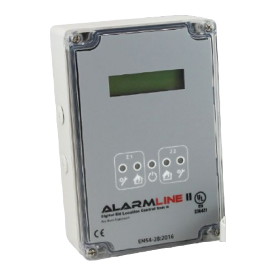
General Overview AlarmLine II Digital EN Controller The Kidde AlarmLine II Digital EN Controller is a dual zone module for each zone. The unit is intended to be installed between the Digital Linear monitoring up to two zones of Kidde AlarmLine II Digital EN Linear Heat Heat Detection cable and a conventional or addressable fire alarm Detection (LHD) Cable. -
Page 5: Technical Specifications
(28AWG) to 4mm (11AWG) Supervised Circuits: Power, Input Zone 1 & Input Zone 2 Inputs: Up to two Class B zones of Kidde AlarmLine II Digital EN LHD Cable ...Max Zone Length 1000m (3,280ft) ...Min Zone Length ...End of line resistor 3.6kohm (included) -
Page 6: Installation
1) The Digital LHD cable can be connected directly to the AlarmLine II Digital EN Controller 2) The Digital LHD cable is connected to a length of leader cable which is connected to the AlarmLine II Digital EN Controller. In this scenario the leader cable must be “calibrated out”... -
Page 7: Operating Modes
There are two operating modes for the AlarmLine II Digital EN Controller: 1. Independent – This is when the AlarmLine II Digital EN Controller is used as a two zone system. When a fault or overheat condition occurs on a Digital LHD zone, the corresponding fault or alarm output respectively is triggered. - Page 8 This mode may also be known as coincidence detection. In this case, the same rated temperature Digital LHD cable should be attached to both zones of the AlarmLine II Digital EN Controller. The alarm output is only activated when both Digital LHD cables trigger an alarm due to an overheat condition. If one Digital LHD cable zone input registers an alarm but the second does not, the alarm output will not be activated.
-
Page 9: Useful Information
Suitable temperature range, or other environmental conditions, where the screws for the type of wall the AlarmLine II Digital EN Controller is to be Digital LHD cable is to be used is greater than the maximum ambient mounted on will need to be provided for separately. -
Page 10: Commissioning
Zone 1 ldr cable hazardous area and IS barriers are being used, the voltage drop to the start of the LHD cable must be measured by the AlarmLine II Digital EN Controller in order to ensure correct operation and accurate distance location. - Page 11 Commissioning (Cont.) 9. If “Yes” was selected in step 8, the AlarmLine II Digital EN Controller will then ask if the zone is ready to be calibrated. Ensure that the connection Ready to between the leader cable and/or the IS barriers and the start of the calibrate? Digital LHD cable is securely shorted out between the two cores.
-
Page 12: Normal Operation
{Zone 2: OK Either of the display screens above and a single flashing Power light (green colour) should be visible when AlarmLine II Digital EN Controller is in normal operation. Page 12 of 17 Revision 1.1 Aug 2020 Document No. -
Page 13: Fault/Alarm Conditions
Fault/Alarm Conditions LED Illustration 21. If an alarm condition occurs the AlarmLine II Digital EN Controller automatically calculates the distance along the cable to the trigger point Zone 1 : 534 m and first displays this value in metres. Zone 2: OK 22. -
Page 14: Testing And Verification
SET and SELECT buttons for 10s or more until the device resets. Interlock mode {Zone 1 : FAUL T {Zone 2: FAUL T Page 14 of 17 Revision 1.1 Aug 2020 Document No. AlarmLine II Digital EN Controller Installation Instructions... -
Page 15: Two-Wire Rs-485 Modbus Rtu/Ascii Communications
The Kidde AlarmLine II Digital EN Controller includes a two wire RS-485 Modbus output which can be enabled to output the status of each zone of Digital Linear Heat Detection cable. The AlarmLine II Digital EN Controller Modbus output supports the Modbus RTU/ASCII protocol and the following functions: •... -
Page 16: Resetting The Alarmline Ii Digital En Controller
Modbus setup will all require selecting after this procedure. To reset the AlarmLine II Digital EN Controller back to the factory state, when the unit is powered up and in normal operation (see step 20 in the Commissioning procedure), press and hold the SET and SELECT buttons for a minimum of 10 seconds continuously. -
Page 17: Glossary
– A non-temperature sensing cable which transmits the signals between two components in the system, e.g. the AlarmLine II Digital EN Controller and the Digital LHD cable. Does not provide fire detection and may be fire-rated to continue functioning even in a fire condition.
Need help?
Do you have a question about the Alarmline II Digital EN and is the answer not in the manual?
Questions and answers