
Related Manuals for Entrematic EMSW


Summary of Contents for Entrematic EMSW
- Page 1 EntreMatic EMSW Installation manual T B 8 AAF293EMA FAA074F0EMEI Issued 2004-12-15...
- Page 2 Issued 2004-12-15 FAA074F0EMEI...
-
Page 3: Table Of Contents
EMSW-2, double door operators ........11... - Page 4 Table of content: Cover ........27 11.1 Fitting and removing the cover .
-
Page 5: Revision
Revision Revision Following pages have been revised: Page Revision Note added for “Kill switch” FAA074F0EMEI Issued 2004-12-15... -
Page 6: Important Information
To avoid bodily injury, material damage and malfunction of the product, the instructions con- tained in this manual must be strictly observed during installation, adjustment, repairs and serv- ice etc. Only EntreMatic trained experts should be allowed to carry out these operations. Radio and television reception This equipment generates and uses radio frequency energy and if not installed and used prop- erly, that is, in strict accordance with the manufacturer’s instructions, may cause interference to... -
Page 7: Introduction
EntreMatic EMSW. The EntreMatic EMSW is suitable for most types of external and internal swing doors. The oper- ator can be mounted to walls on either side of the door for pull or push action and is suitable for single or double doors fitted with butt hinges or pivots. -
Page 8: Function Description
Function description Function description The EntreMatic EMSW works electro-hydraulically. It opens with an AC-motor that via a hydraulic unit and an arm system transmits the power to the door leaf. The closing power is from a coil spring. The movement of the door is controlled by limit switches and valve screws. -
Page 9: Technical Specifications
Arm system PULL / PULL-P: 100 kg for door leaf width 1400 mm (higher door weights on request) The EMSW complies with Controlled door closing, EN 1154 size 3-6 the door weights/widths Electrically powered hold-open device for swing doors, EN... -
Page 10: Models
The operators are non-handed and not dependent on the hinges. The operators suit both pushing and pulling arm systems. EMSW, standard cover wall mounted EMSW is the standard operator. Pushing arm system on a wall-mounted and on a door leaf- mounted operator shown. Wall-mounted... -
Page 11: Emsw-Spec, Cover With Optional Length (Wall-Mounted)
AAF273EMA EMSW-2, double door operators The designation EMSW-2 means that two operators are mounted under the same cover to open one door each. The length L and the cut-outs R and S must be specified in the order. Pushing and pulling arm system shown. It is also possible to use two pushing or two pulling arm systems. -
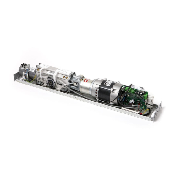
Page 12: Part Identification & Accessories
Part identification & Accessories Part identification & Accessories T B 8 AAF291EMA (1) Mounting plate Cable inlet (12) Cover = Centre line, drive C L1 shaft (2) Motor/pump Mains connection (13) Bearaing = Centre line, hinge C L2 (3) Magnetic Valve Control unit, CSDA (14) Cable holder (4) Hydraulic unit... - Page 13 Part identification & Accessories Tool kit to change 3-Position Door stop rotation direction Switch PS-3A Art. No. 100147 Art. No. 173719 Limit Switch Art. No. 600080 Art. No. 655614 Coordination unit, COOA PULL-Arm Reveal Spacer Art. No. 100091 Art. No. 173804BK for PULL Art.
-
Page 14: Further Accessories
Part identification & Accessories Further Accessories Mounting plate For reinforcement of the wall: 160 x 8 mm (Art. No. 173661) Heavy duty pulling arm system ST-V/H Activation units see separate installation instructions Drilling template (Art. No. 1000219) Push & Go (PAG) (Art. -
Page 15: Mechanical Installation
Mechanical installation Mechanical installation This instruction comprises the installation of the EntreMatic EMSW with arm systems PUSH which push the door open and PULL which pull the door open. Always make sure, before commencing the installation, that the door leaf and the wall are prop- erly reinforced at the fixing points. -
Page 16: Wall-Mounted Operator With Arm System Push
Mechanical installation Wall-mounted operator with arm system PUSH 8.1.1 Establish the installation height Establish the installation height X which is the distance from the underside of the wall to the underside of the mounting plate. Mark distance X on the wall. X can be between 2 – 87 mm depending on the shaft extension used;... -
Page 17: Mounting The Drive Arm
Mechanical installation 8.1.4 Mounting the drive arm 1 Mount the drive arm and adaptor on the operator drive shaft at an angle of 90° to the wall. 2 Ensure that the teeth of the adaptor engage fully with the operator shaft but especially with the drive arm, so they are not damaged when the drive arm is tightened. -
Page 18: Wall Mounted Operator With Arm System Pull / Pull-P
Mechanical installation Wall mounted operator with arm system PULL / PULL-P If the operator is not ordered as an “operator package with arm system PULL / PULL-P” the direction of rotation must be reversed. 8.2.1 Changing the direction of rotation 1 Mount the washers and screws in the drive shaft, one from each side. -
Page 19: Establish The Installation Height
Mechanical installation 8.2.2 Establish the installation height Establish the installation height Z which is the distance from the top of the door to the underside of the mounting plate. Mark distance Z on the wall. Z can be 46, 66, 96 or 116 mm depending on whether a shaft extension is used or not. 8.2.3 Mounting the drive unit 1 Put the template to the wall aligned with the hinges and with the underside of the mounting... -
Page 20: Mounting The Drive Arm And Door Fitting
Mechanical installation 8.2.4 Mounting the drive arm and door fitting 1 Connect the mains power (see page 19). 2 Open the door to an angle of 90°. 3 Give constant impulse by strapping the impulse inputs on the control unit. The drive shaft turns to a factory-set position.
Need help?
Do you have a question about the EMSW and is the answer not in the manual?
Questions and answers