
Related Manuals for Turtle Tough TT-HFC

Summary of Contents for Turtle Tough TT-HFC
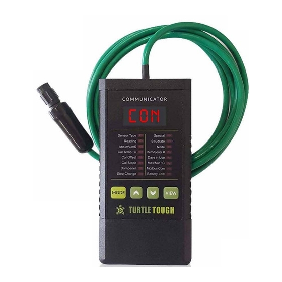
- Page 1 TURTLE ® TOUGH MANUAL DSS HANDHELD FIELD COMMUNICATOR Conductivity C O N TURTLE ® turtletoughsensors.com TOUGH...
-
Page 2: Specifications
DSS Smart Digital RS485 Modbus RTU sensors at any location. All values stored in non- volatile sensor EEPROM for hot-swap portability when installed back into field service. Product name DSS HandHeld Field Communicator - Conductivity Code TT-HFC Mechanical Housing Mounting Handheld IP Class Housing IP40... - Page 3 Programming and Navigation The Handheld Field communicator (HFC) has 3-digit display and 16 LEDs to show readings and analytic data as well as to calibrate and configure sensor. Programming done by 4 key front panel. ‘Mode’ key used to toggle and navigate to each LED.
- Page 4 Intelligent DSS Handheld Field Communicator for Calibration, Configuration, Spot Measurement and Troubleshooting of Smart Digital RS485 Modbus RTU Conductivity DSS Sensors LED LABEL Parameter Description and Method to Access Range Default Load options for connected sensor pH or ORP or DO or ISE or CON ‘View’...
- Page 5 Color notes Parameters in light green are defined by factory at dispatch time or determined from field use. Parameters in grey can be adjusted as desired. Parameters in dark green are obtained from wet calibrations done with DSS sensor in the field. Scaling Display Notes When reading is less than 1.00 mS/cm the value will flash indicating that the units are in μS/cm instead of mS/cm.
- Page 6 Setup of DSS RS-485 Modbus RTU Sensor to Handheld Field Communicator 1. Press the ‘Mode’ button to turn on HFC. The HFC will attempt to communicate with the last used baudrate and node address. If either no sensor is connected or available at the last used baudrate and node address then three dashes “---”...
- Page 7 Sensor Serial Number, Item Number and Total Time in Field Service Systematic tracking achieved with factory stamped sensor serial and item number. The internal clock on the DSS sensor board is incremented when energized to monitor the total number of days in active field service. If the sensor is disconnected the incrementing of the time in service will stop.
- Page 8 Display Features Available Using The ‘View’ Key • In ‘Node’ mode press ‘View’ key to invoke the node scanning feature (see Instructions for node scanning and changing node - page 6).* • In ‘Baud Rate’ mode press ‘View’ key for 3 to 5 seconds to invoke node changing mode (see Instructions for node scanning and changing node - page 6).* •...
- Page 9 Modbus RTU setup of DSS sensor is available to enable all functionality detailed below. READ-ONLY Data Core Process Value Description READ-ONLY Data Analytic Sensor Value Description Conductivity sent as 0 to 50,000 1 - DSS-pH steps for all cell constants & range 2 - DSS-ORP Standard Range modes.
- Page 10 Conductivity Cell Constant and Available Range Modes for Smart DSS Sensors with RS-485 STANDARD RANGE MODE * - in microSiemens/cm Range Scaling Factor 200 Max Temp. Compensated Conductivity using 2% per OC Coefficient Max Raw Lowest Recommended Cell Constant (K) Resolution @ 25OC @ 75OC...
- Page 11 Conductivity Cell Constant and Available Range Modes for Smart DSS Sensors with RS-485 ULTRA-LOW RANGE MODE * - in microSiemens/cm Range Scaling Factor 2 Max Temp. Compensated Conductivity using 2% per OC Coefficient Max Raw Lowest Recommended Cell Constant (K) Resolution @ 25OC @ 75OC...
- Page 12 Ultralow Range Conductivity Sensors for Ultrapure Water (UPW) The conductivity of pure water varies significantly with temperature in a well defined but non-linear fashion as detailed in the graph to left. This behavior is preprogrammed into the DSS-CON-L Modbus RTU conductivity sensors for the automatic temperature compensation feature to make it suitable for ultrapure water (UPW) type applications.
Need help?
Do you have a question about the TT-HFC and is the answer not in the manual?
Questions and answers