Roving Networks RN-131G Manual
Wifly gsx 802.11 b/g wireless lan module
Hide thumbs
Also See for RN-131G:
- User manual and command reference (68 pages) ,
- User manual and command reference (23 pages) ,
- Manual (19 pages)
Table of Contents
Advertisement
Quick Links
www.rovingnetworks.com
WiFly GSX 802.11 b/g
Wireless LAN Module
Features
Qualified 2.4GHz IEEE 802.11b/g transceiver
High throughput, 1Mbps sustained data rate
with TCP/IP and WPA2
Ultra-low power - 4uA sleep, 40mA Rx,
210mA Tx (max)
Small, compact surface mount module
On board ceramic chip antenna and U.FL
connector for external antenna
8 Mbit flash memory and 128 KB RAM
UART hardware interface
10 general purpose digital I/O
8 analog sensor interfaces
Real-time clock for wakeup and time stamping
Accepts 3.3V regulated or 2-3V battery
Supports Adhoc connections
On board ECOS -OS, TCP/IP stacks
Wi-Fi Alliance certified for WPA2-PSK
FCC / CE/ ICS certified and RoHS compliant.
Industrial (RN-131G) and commercial
(RN-131C ) grade temperature options
Applications
Remote equipment monitoring
Telemetry
Industrial sensors and controls
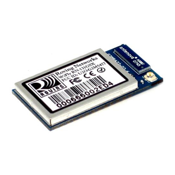
On-board
On-board
chip antenna
chip antenna
U.FL connector
U.FL connector
For optional external
For optional external
antenna
antenna
809 University Avenue
2.4 GHz
2.4 GHz
TX/RX
TX/RX
X
X
PA
PA
accelerator
accelerator
Sensor Interface
Sensor Interface
•
•
Los Gatos, CA 95032
~ page 1 ~
RN-131G & RN-131C
RN-131-DS v2.6 10/5/2011
Home Automation
Medical device monitoring
Description
The WiFly GSX module is a stand alone, embedded
wireless 802.11 networking module. Because of its
small form factor and extremely low power
consumption, the RN-131G is perfect for mobile
wireless applications such as asset monitoring, GPS
tracking and battery sensors. The WiFly GSX module
incorporates a 2.4GHz radio, processor, TCP/IP stack,
real-time clock, crypto accelerator, power
management and analog sensor interfaces. This
complete solution is preloaded with software to
simplify integration and minimizes development of
your application. In the simplest configuration the
hardware only requires four connections (PWR, TX,
RX, GND) to create a wireless data connection.
Additionally, the sensor interface provides
temperature, audio, motion, acceleration and other
analog data without requiring additional hardware. The
WiFly GSX module is programmed and controlled with
a simple ASCII command language. Once the WiFly
GSX is setup it can scan to find an access point,
associate, authenticate and connect over any WifI
network.
Block Diagram
128KB
128KB
32-bit
32-bit
RAM
RAM
CPU
CPU
2.4 GHz
2.4 GHz
Radio
Radio
802.11b/g
802.11b/g
MAC/PHY
MAC/PHY
2.4 GHz
2.4 GHz
PA
PA
Pwr
Pwr
ADC
ADC
Crypto
Crypto
Mgmt
Mgmt
EPC/RFID
EPC/RFID
• info@RovingNetworks.com
Tel (408) 395-6539
Flash
Flash
2MB
2MB
Memory
Memory
ROM
ROM
timers
timers
SPI
SPI
GPIO
GPIO
SDIO
SDIO
3.3V Boost
3.3V Boost
Regulator
Regulator
SPI
SPI
GPIO
GPIO
UART
UART
VDD IN
VDD IN
VDD BATT
VDD BATT
Boost
Boost
Enable
Enable
Advertisement
Table of Contents

Subscribe to Our Youtube Channel
Related Manuals for Roving Networks RN-131G


Summary of Contents for Roving Networks RN-131G
- Page 1 On board ceramic chip antenna and U.FL small form factor and extremely low power connector for external antenna consumption, the RN-131G is perfect for mobile 8 Mbit flash memory and 128 KB RAM wireless applications such as asset monitoring, GPS ...
-
Page 2: Environmental Conditions
RN-131G & RN-131C www.rovingnetworks.com RN-131-DS v2.6 10/5/2011 Overview Host Data Rate up to 1 Mbps for UART Intelligent, built-in power management with programmable wakeup Can be powered from regulated 3.3-3.7V source or 2.0-3.0V batteries Real time clock for time stamping, auto-sleep and auto-wakeup ... -
Page 3: Radio Characteristics
RN-131G & RN-131C www.rovingnetworks.com RN-131-DS v2.6 10/5/2011 Analog Sensor Inputs Parameter Value Sense 0,1,2,3 wakeup detect threshold 500mV AD sense 0-7 measurement range 0-400mV Precision 14 bits = 12uV Accuracy 5% un-calibrated, .01% calibrated Minimum conversion time 35uS (5kHz over wifi ) Sensor Power (pin 33) output resistance 3.3V... -
Page 4: Typical Application Schematic
RN-131G & RN-131C www.rovingnetworks.com RN-131-DS v2.6 10/5/2011 Typical Application Schematic P3_3V LED_RED LED_GREEN • • • info@RovingNetworks.com 809 University Avenue Los Gatos, CA 95032 Tel (408) 395-6539 ~ page 4 ~... -
Page 5: Pin Description
INPUT: RX in to the module, 3.3V tolerant UART-TX OUTPUT: TX out from the module, 8mA drive, 3.3V tolerant SPI-MOSI SPI master data out (Contact Roving Networks for details) No connect SPI-CLK SPI clock, (Contact Roving Networks for details) No connect... -
Page 6: Physical Dimensions
RN-131G & RN-131C www.rovingnetworks.com RN-131-DS v2.6 10/5/2011 20 mm 20 mm 20 mm 2.5 mm 2.5 mm 2.5 mm 2.5 mm 2.5 mm 2.5 mm 37 mm 37 mm 37 mm RN131G RN131G RN131G Ceramic chip Ceramic chip U.FL U.FL... - Page 7 RN-131G & RN-131C www.rovingnetworks.com RN-131-DS v2.6 10/5/2011 Design Concerns 1. Minimizing radio interference. When integrating the WiFly module with on board chip antenna make sure the area around the chip antenna end the module protrudes at least 6mm from the mother board PCB and any metal enclosure.
- Page 8 3. Solder Reflow. Reflow temperature must not exceed 220C. To reflow solder the RN-131G and RN-131C module onto a PCB Roving recommends a RoHS compliant solder paste equivalent to the NIHON ALMIT paste or OMNIX OM-310 solder paste from Alpha metals.
- Page 9 RN-131G & RN-131C www.rovingnetworks.com RN-131-DS v2.6 10/5/2011 • • • info@RovingNetworks.com 809 University Avenue Los Gatos, CA 95032 Tel (408) 395-6539 ~ page 9 ~...
- Page 10 RN-131G & RN-131C www.rovingnetworks.com RN-131-DS v2.6 10/5/2011 4. U.FL connector. Use Hirose U.FL connector U.FL-R-SMT to for connecting external antennas. See Roving Networks U.FL to SMA cable. Part number: RN-UFL-SMA6 5. Connection Status. GPIO-4, GPIO-5, GPIO-6 are available to drive a status LEDs. GPIO-4 indicates TCP/IP connection status.
- Page 11 RN-131G & RN-131C www.rovingnetworks.com RN-131-DS v2.6 10/5/2011 8. Reset (Pin 5). The RESET signal is used to reset the module and is ACTIVE low. This pin has a built in 100k pull up. It is not required to connect this pin and it can be left unconnected. To reset the module a pulse of 160us minimum duration at 3.3V must be applied.
- Page 12 RN-131G & RN-131C www.rovingnetworks.com RN-131-DS v2.6 10/5/2011 Conditions Operation is subject to the following conditions This device may not cause harmful interference This device must accept any interference received, including interference that may cause undesired operation. Markings To satisfy the FCC exterior labeling requirements the following text must be placed on the exterior of the end...
-
Page 13: Compliance Information
RN-131G & RN-131C www.rovingnetworks.com RN-131-DS v2.6 10/5/2011 NCC (Taiwan statement) Contains Transmitter Module NCC ID: CCAF11LP0240T6 802.11b/802.11g/BT 警 語 : 第 十 二 條 →經 型 式 認 證 合 格 之 低 功 率 射 頻 電 機 , 非 經 許 可 , 公 司 , 商 號 或 使 用 者 均 不 得 擅 自 變 更 頻 率 、 加 大 功 率 或 變 更 原 設 計 之 特 性 及 功 能 。... -
Page 14: Ordering Information
Roving Networks products are not authorized for use in safety-critical applications (such as life support) where a failure of the Roving Networks product would reasonably be expected to cause severe personal injury or death, unless officers of the parties have executed an agreement specifically governing such use.
Need help?
Do you have a question about the RN-131G and is the answer not in the manual?
Questions and answers