Table of Contents
Advertisement
Quick Links
Assembly Instructions for SCA6x0 and SCA10x0 series
TABLE OF CONTENTS
Table of Contents .....................................................................................................................1
1 Objective ..............................................................................................................................2
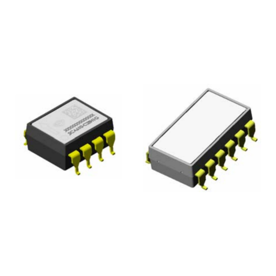
2 VTI'S DIL-8 and DIL-12 packages.......................................................................................2
3 Package Outline and Dimensions......................................................................................2
4 Tape and reel specifications ..............................................................................................3
5 Printed Circuit Board (PCB) Level Guidelines ..................................................................5
5.1
Recommended PCB pad layout................................................................................................5
5.2
Solder paste and Cleaning process .........................................................................................5
5.3
Stencil .........................................................................................................................................6
5.4
Paste printing .............................................................................................................................6
5.5
Component picking and placement .........................................................................................6
5.6
Reflow soldering ........................................................................................................................6
5.7
Moisture sensitivity level (MSL) classification........................................................................7
5.8
Inspection ...................................................................................................................................8
6 Hand Soldering Guidelines ................................................................................................9
7 Rework Guidelines ............................................................................................................10
7.1
Instructions for desoldering and removing of component..................................................10
8 Environmental Aspects ....................................................................................................11
9 References.........................................................................................................................11
10 Document Change Control...............................................................................................12
Technical Note 71
Advertisement
Table of Contents

Summary of Contents for VTI For SCA6 0 Series SCA10 0 Series
-
Page 1: Table Of Contents
Assembly Instructions for SCA6x0 and SCA10x0 series TABLE OF CONTENTS Table of Contents ........................1 1 Objective ..........................2 2 VTI'S DIL-8 and DIL-12 packages..................2 3 Package Outline and Dimensions..................2 4 Tape and reel specifications ....................3 5 Printed Circuit Board (PCB) Level Guidelines ..............5 Recommended PCB pad layout....................5... -
Page 2: Objective
Objective This document provides general guidelines for Printed Circuit Board (PCB) design and assembly of VTI's surface mountable DIL type of Pre-molded Lead-frame packages (DIL-8 for SCA6x0 series and DIL-12 for SCA10x0 series). It should be emphasized that this document serves only as a design guideline to help develop the optimal assembly conditions. -
Page 3: Tape And Reel Specifications
Packing tape dimensions are presented in figure 4. The unreeling direction and component polarity on tape are presented in figure 5. Reel dimensions are presented in figure 6. Figure 4: Packing tape dimensions for the DIL-8 and DIL-12 package. All dimensions in millimeters (mm). VTI Technologies Oy 3/12 www.vti.fi Rev.1.0... - Page 4 Figure 5: Package orientation on the tape and unreeling direction on tape. DRAWING FOR REFERENCE ONLY N min W 2max 24.4 ± 2 Ø13.0 ± 0.25 30.4 Figure 6: Reel dimensions. All dimensions in millimeters (mm). VTI Technologies Oy 4/12 www.vti.fi Rev.1.0...
-
Page 5: Printed Circuit Board (Pcb) Level Guidelines
Printed Circuit Board (PCB) Level Guidelines 5.1 Recommended PCB pad layout For optimal soldering and solder joint reliability results of VTI's DIL component, the PCB terminal pads should be designed larger than the package leads. Reference dimensions for the land pad design are presented in Figure 7. -
Page 6: Stencil
Too much solder paste can cause bridging and too little solder paste can cause insufficient wetting or open solder joint. Generally the stencil thickness needs to be matched to the needs of all components on the PCB taking account the co-planarity spec of VTI's DIL components. -
Page 7: Moisture Sensitivity Level (Msl) Classification
3. After bag is opened, devices that will be subjected to reflow solder or other high temperature process must be a) Stored at <10% RH, b) Mounted within 168 hours of factor conditions ≤30 °C/60%RH. Note: Do not re-store devices that have exposed >10% RH conditions. VTI Technologies Oy 7/12 www.vti.fi Rev.1.0... -
Page 8: Inspection
An example of a DIL solder joint cross-section in presented in Figure 9. mag. mag. mag. Figure 9: Cross-section of the DIL package lead's solder joint (with eutectic SnPb solder). VTI Technologies Oy 8/12 www.vti.fi Rev.1.0... -
Page 9: Hand Soldering Guidelines
PCB pad and through that the heat should be conducted to the tin wire and component lead. VTI has used 315ºC setting temperature for component soldering. The temperature on the tip of the tool is 270...275ºC. -
Page 10: Rework Guidelines
If hot air rework station is not available, rework with thermal tweezers is also an acceptable alternative. This method is used at VTI e.g. for failure analysis purposes. This technical note describes VTI's rework procedure. Removing of the component with hot iron only is difficult as it is easy to get the part too hot and destroy it. -
Page 11: Environmental Aspects
VTI does not recommend rework. Environmental Aspects VTI Technologies respects environmental values and thus, its DIL packages are lead-free and RoHS compatible. VTI Technologies’ sensors should be soldered with lead-free solders in order to guarantee full RoHS compatibility. References JEDEC / Electronic Industries Alliance, Inc. -
Page 12: Document Change Control
Assembly Instructions for SCA6x0 and SCA10x0 series TN71 10 Document Change Control Version Date Change Description 22.04.2008 Release VTI Technologies reserves all rights to modify this document without prior notice. VTI Technologies Oy 12/12 www.vti.fi Rev.1.0...
Need help?
Do you have a question about the For SCA6 0 Series SCA10 0 Series and is the answer not in the manual?
Questions and answers